OVERVIEW
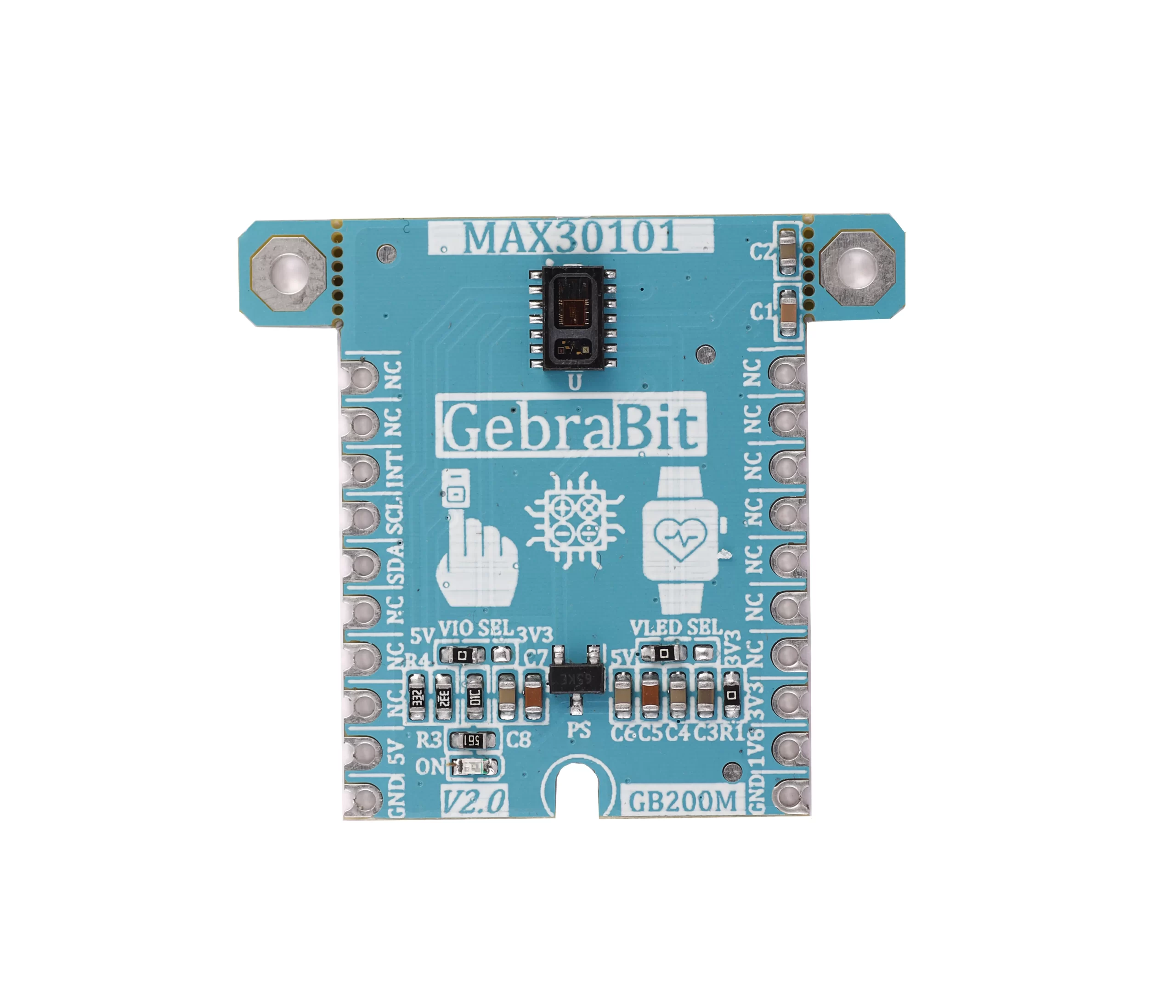
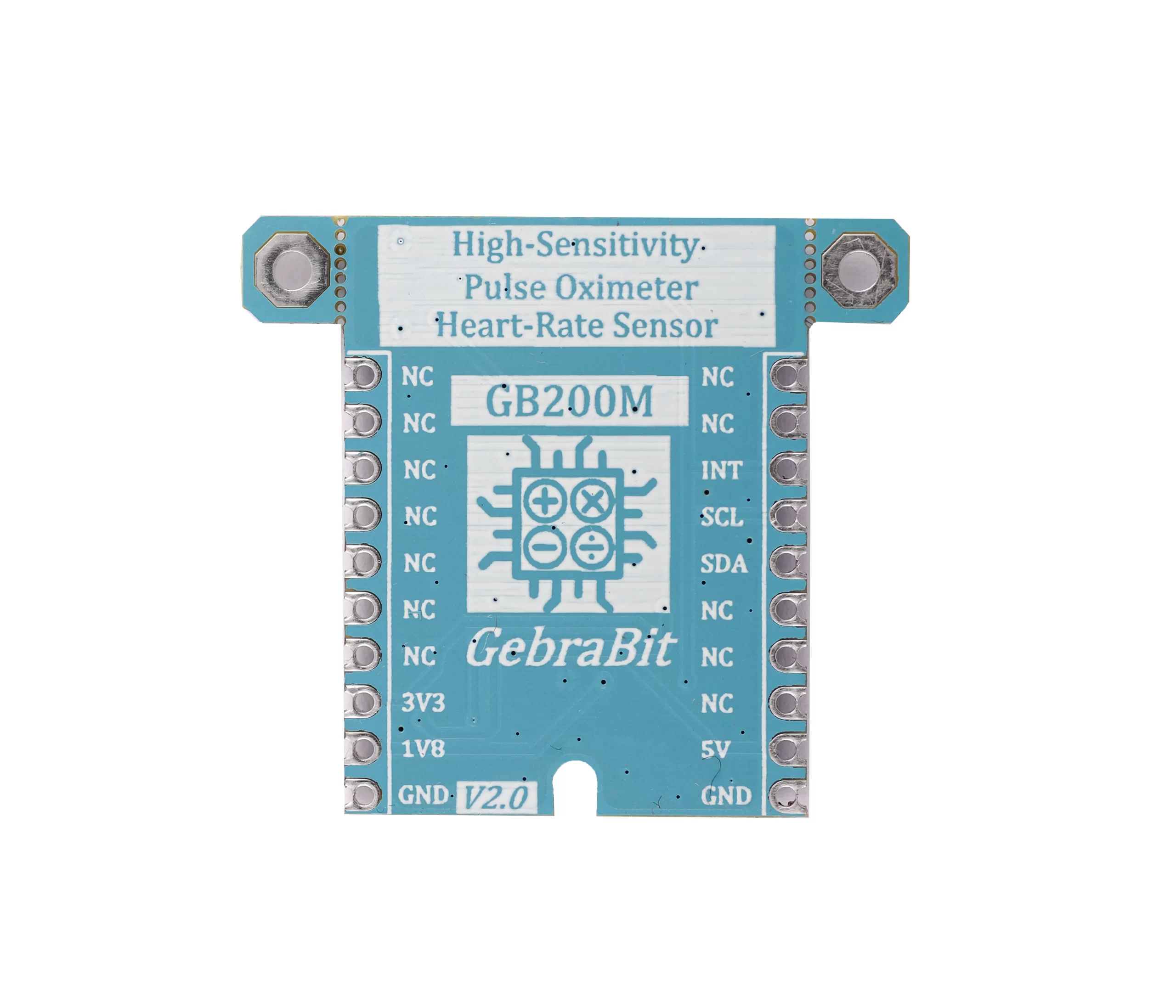
GebraBit MAX30101 is integrated pulse oximetry and a heartrate monitor module.
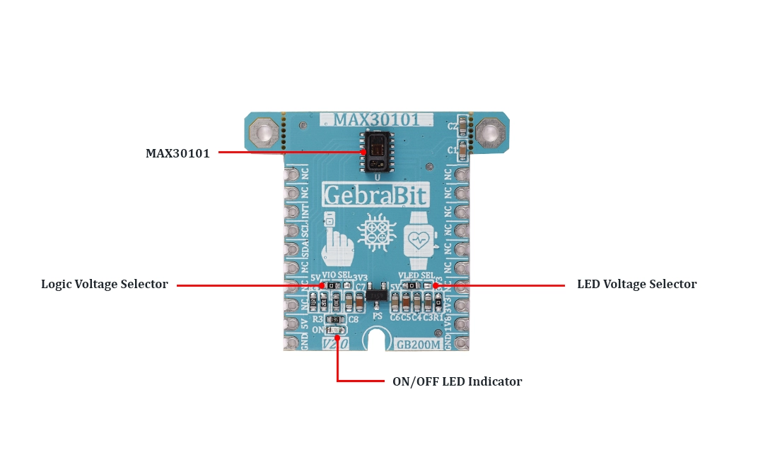
GebraBit MAX30101 module, due to an integrated 1V8 regulator, turns the MAX30101 sensor ON. The regulator output is accessible on the “1V8” pin. Also, there is two jumper selector on the GebraBit MAX30101 module; One is “VLED SEL” which determines MAX30101 LED Anode Supply Voltage between “5V” or “3V3”.The other jumper is “VIO SEL” which is regarded to select logic level voltage of module between “5V” or “3V3”.This feature helps to use a wide range of microcontrollers for interfacing with this module.
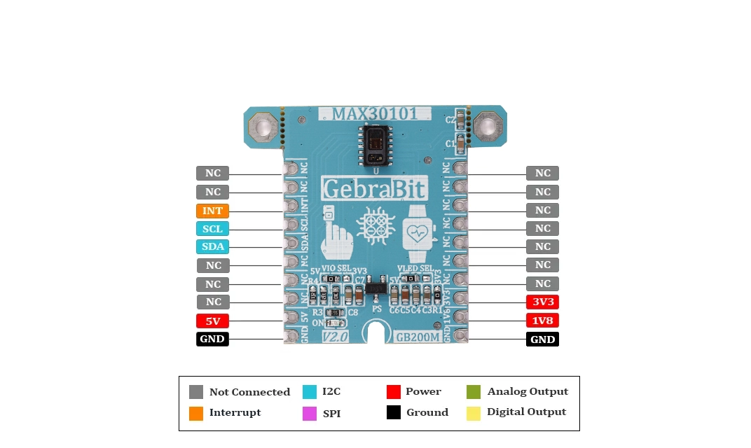
An important note about GebraBit MAX30101 is that this module is Pin Compatible with GEBRABUS , and the “INT” pin of MAX30101 is available. Users can interface with GebraBit MAX30101 by I2C protocol to get data and configure the sensor.
MAX30101 is integrated pulse oximetry and heartrate monitor module. It includes internal LEDs, photodetectors, optical elements, and low-noise electronics with ambient light rejection. The MAX30101 provides a complete system solution to ease the design-in process for mobile and wearable devices. The MAX30101 operates on a single 1.8V power supply and a separate 5.0V power supply for the internal LEDs. Communication is through a standard I2C-compatible interface. The module can be shut down through software with zero standby current, allowing the power rails to remain powered at all times.
WARNING: FOR ACCURATE INFORMATION ABOUT ICs ABSOLUTE MAXIMUM RATINGS AND ITS PRECIOUS CHARACTERISTICS RANGES, USERS MUST CERTAINLY REFER TO ICs MANUFACTURE DATASHEET.
Key Features
- User-selectable module logic level voltage
- User-selectable MAX30101 LED Anode Supply Voltage
- 1V8 Voltage Regulator
- 1V8 Output Voltage
- On Board, ON/OFF LED indicator
- Pin Compatible with GEBRABUS
- I2C protocol to get data and configure the sensor
- GebraBit small package
- It can be used as a daughter board of GEBRABIT MCU Modules
- Featuring Castellated pad (Assembled as SMD Part)
- Separatable screw parts to reduce the size of the board
Pinout Diagram
Module Overview
Documents Link
Project and Source Code

Schematic (.Pdf)

Module Layout (.Pdf)

MAX30101 Datasheet

Module Overview

