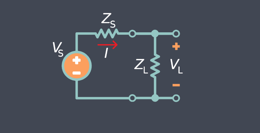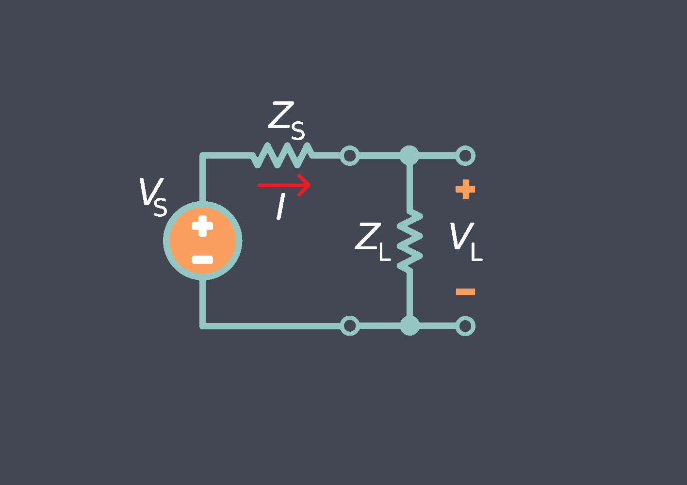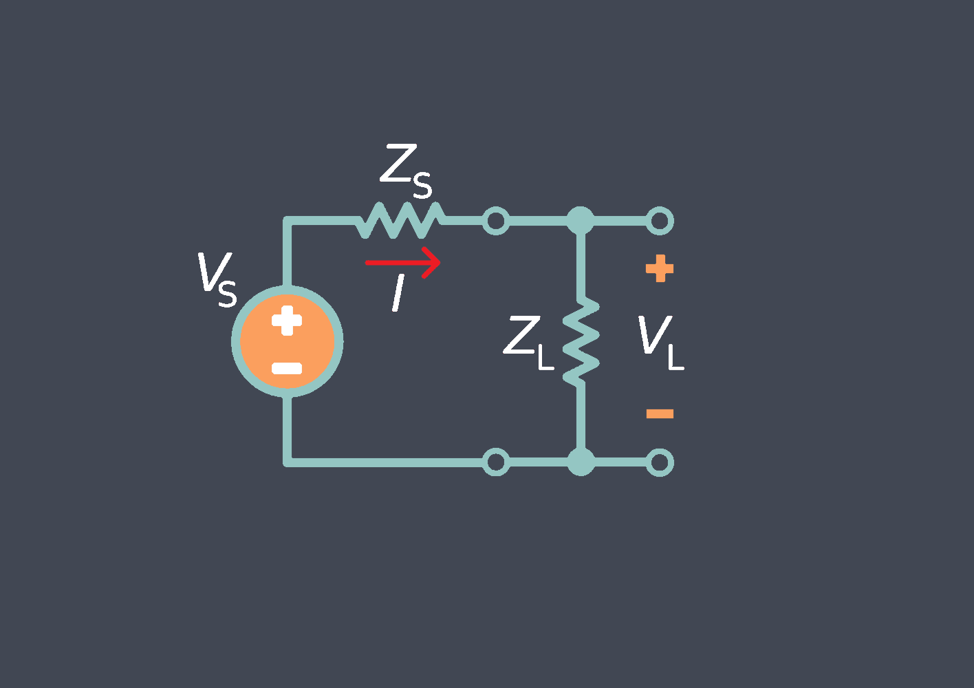
Output impedance refers to the resistance of the sensor to the flow of current to the output signal. It represents the internal resistance of the sensor’s output circuitry that interacts with the load impedance of the receiving device or system.
Sensor output impedance refers to the electrical resistance of the sensor’s output circuitry. It is an important characteristic to consider when integrating sensors into a larger electronic system.
The output impedance affects how the sensor’s signal is transmitted and received by other components in the system. A low output impedance means that the sensor can drive a stronger signal and can more easily deliver its output voltage or current to subsequent stages in the circuit without significant loss.
On the other hand, a high output impedance can result in signal degradation, especially when connected to external devices with higher input impedance. This can lead to signal loss, distortion, or inaccuracies in the final measurement or control process.
One common example is the use of sensors in transducers or measurement circuits. If the output impedance of the sensor is high relative to the input impedance of the following amplifier or data acquisition system, it can attenuate or alter the signal, introducing errors or reducing the overall accuracy of the measurement.
Types of the output impedance of a sensor
Low output impedance
Many modern sensors, such as active electronic sensors or sensors with built-in amplifiers, have low output impedance. Low output impedance means that the sensor can provide a relatively high amount of current to the load without significant voltage drop.
High output impedance
Some sensors, particularly passive sensors, may have high output impedance. High output impedance means that the sensor’s ability to supply current is limited, resulting in a larger voltage drop when connected to a load. It is crucial to consider this impedance when connecting the sensor to a receiving device with a high input impedance to avoid signal loss or distortion.
Variable output impedance
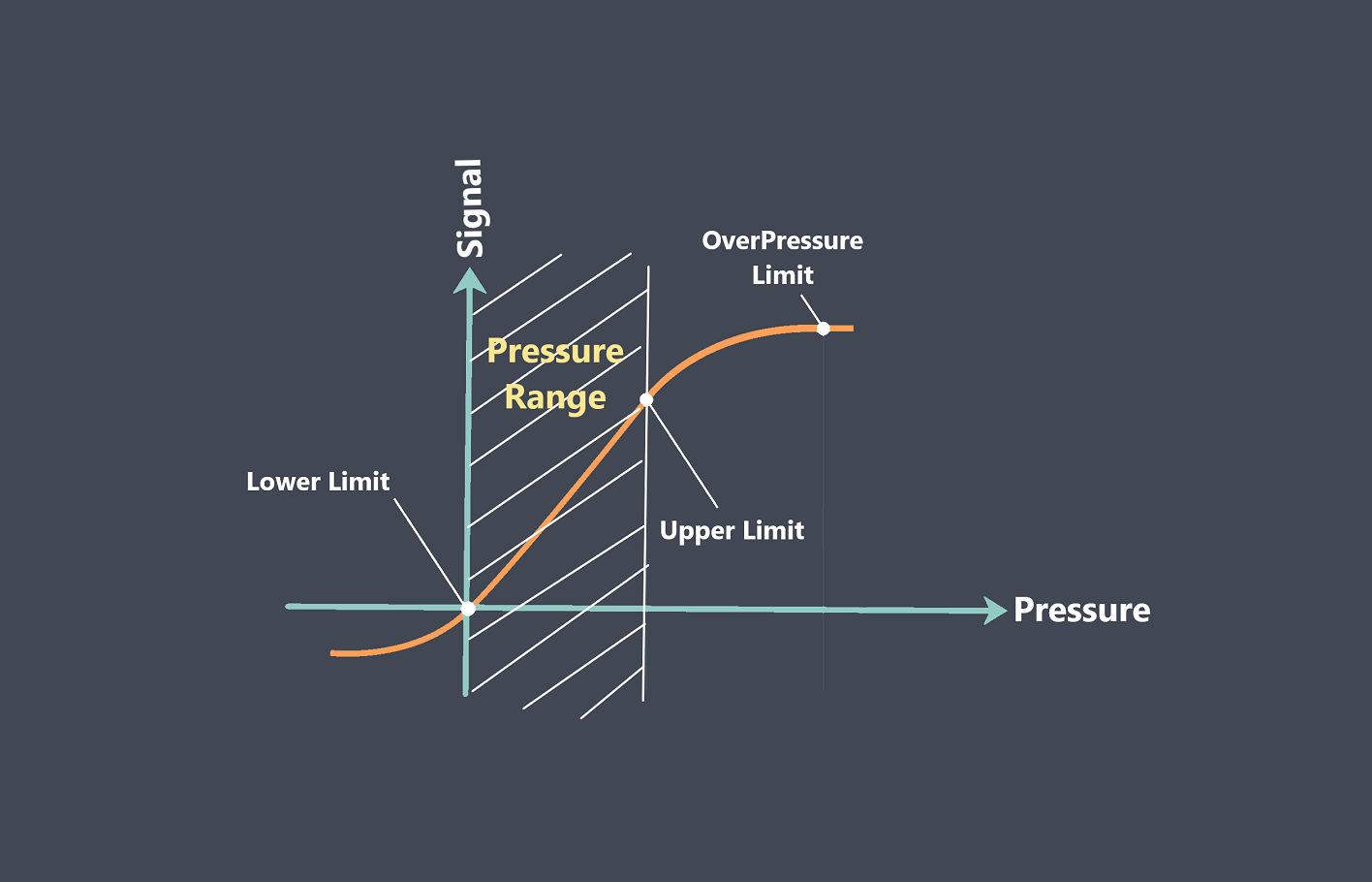
Certain sensors, like variable resistive or variable capacitive sensors, can have variable output impedance based on the measured parameter. For example, in some pressure sensors, the output impedance might change with different pressure levels.
Complex impedance
Some sensors, especially those using reactive elements like inductive or capacitive sensors, can have complex impedance. Complex impedance consists of both resistance and reactance components, often including phase differences between voltage and current. This type of impedance requires careful consideration and matching techniques to ensure proper signal transmission.
How does sensor output impedance affect signal transmission?
The output impedance of a sensor plays a crucial role in signal transmission. Here are a few ways it can affect the transmission of the signal:
Signal Loss
When the output impedance of a sensor is significantly higher than the input impedance of the receiving device, signal loss can occur. This is because the high output impedance creates a voltage divider effect, causing a portion of the signal to be dropped across the internal resistance of the sensor instead of being transmitted to the receiving device.
Attenuation
In cases where the output impedance is mismatched with the input impedance of the receiving device, signal attenuation can occur. The mismatch causes reflections and impedance mismatch losses, resulting in a weakened or distorted signal reaching the receiver.
Distortion
High output impedance can introduce signal distortion due to the interaction between the source impedance and the input impedance of the receiving device. This can manifest as changes in the amplitude, phase, or frequency response of the signal.
Noise Interference
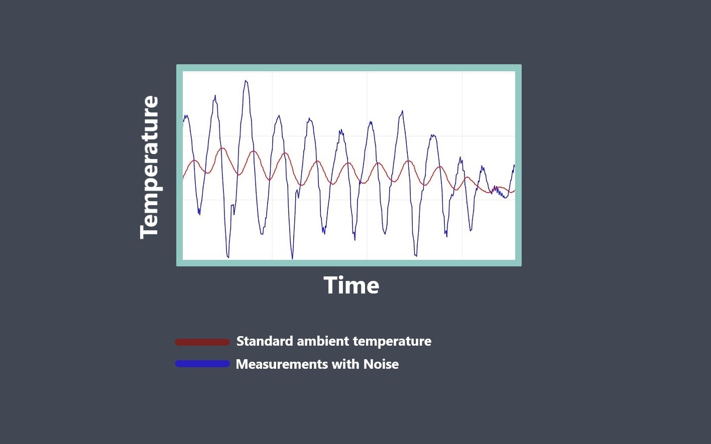
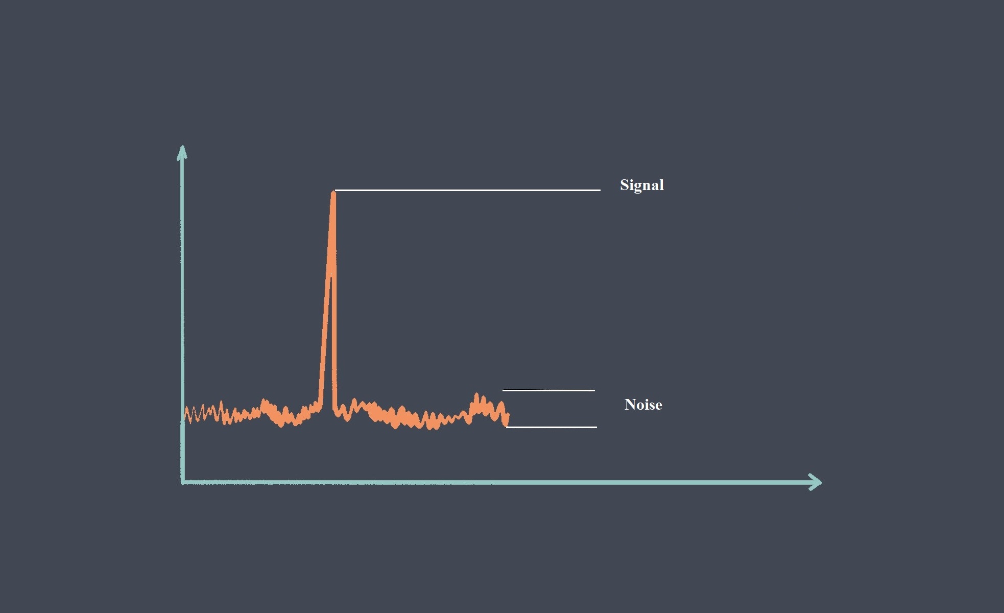
When the output impedance is high, it becomes more susceptible to noise interference from external sources, such as electromagnetic fields or electromagnetic radiation. This interference can degrade the quality and accuracy of the transmitted signal.
To ensure accurate and reliable signal transmission, it is important to match the output impedance of the sensor as closely as possible to the input impedance of the receiving device. This can be achieved through impedance matching techniques or by using amplifiers or buffering circuits to lower the output impedance of the sensor.
Some techniques to match the output impedance of a sensor to the input impedance of a receiving device
Matching the output impedance of a sensor to the input impedance of a receiving device is essential for minimizing signal loss and maximizing the transfer of power. Here are some techniques to accomplish impedance matching:
Use a matching network
A matching network, such as an L-section network or a pi-section network, can be added between the sensor and the receiving device. This network adjusts the impedance to match the desired values by using discrete components like resistors, capacitors, and inductors.
Transformers
If the impedance mismatch is significant, transformers can be used to step up or step down the impedance levels. Transformers can provide electrical isolation as well as impedance matching.
Impedance matching circuitry
Integrated circuits (ICs) specifically designed for impedance matching purposes can be used. These ICs often combine multiple components into a single package, simplifying the matching process.
Buffer amplifiers
Buffer amplifiers can be used to isolate the sensor from the receiving device and provide a low-output impedance source that matches the input impedance of the receiving device.
Active filters
Active filters can be employed to shape the frequency response and match impedance simultaneously. They can provide gain as well as impedance matching functionality.
Resistor networks
Series and parallel resistor networks can be configured to achieve impedance matching. By selecting appropriate resistance values, the output impedance of the sensor can be matched to the input impedance of the receiving device.

