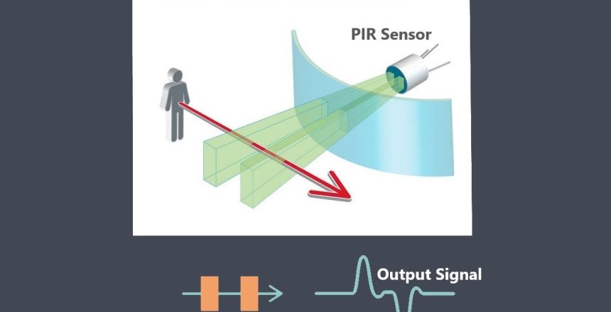
The output signal of a sensor refers to the type of electrical signal it generates in response to the input signal. Sensors can produce various types of output signals, including analog, digital, or frequency-based signals. The choice of output signal depends on the sensor’s design and the requirements of the application.
A sensor output signal refers to the electrical or digital signal generated by a sensor in response to the physical or environmental phenomenon it is designed to measure. In fact the nature of the signal depends on the type of sensor and its technology. In other word Sensors can generate different types of output signals depending on their design and application. Here are some common types of output signals generated by sensors:
Analog output signal
An analog output refers to a type of signal or data that represents continuous and varying values. In the context of electronics and computer systems, analog output typically refers to signals that are generated by devices like digital-to-analog converters (DACs) or analog output modules. An analog output can take various forms depending on the application.
It could be a voltage level, current value, or a continuous waveform that represents a specific parameter such as sound, temperature, pressure, or motion. These signals are typically used to interface with external devices that require analog input to perform their functions. For example, in a music synthesizer, an analog

output may produce varying voltages that correspond to different musical notes or sound effects. Similarly, in industrial automation, analog outputs may control motor speeds, valve positions, or regulate temperature by producing analog signals proportional to the desired setpoints.
To summarize, an analog output is a continuous signal that represents changing values and is commonly used to interface with external devices that require analog inputs for processing or control purposes.
Analog sensors typically produce continuous voltage or current signals that vary proportionally with the measured quantity. For example, a temperature sensor may provide an analog voltage signal ranging from 0V to 5V, where each voltage value corresponds to a specific temperature value within the measurable range.
Digital output signal
Digital sensors produce discrete digital signals that represent binary states, usually in the form of high (1) or low (0) voltage levels. These sensors often use digital protocols such as I2C, SPI, or UART to communicate with microcontrollers or other devices. The digital signals can convey information such as presence/absence, on/off status, or specific data values.

Some sensors combine both analog and digital outputs. They may have analog outputs for continuous measurements and additional digital outputs for specific conditions or alarms.
Pulse Width Modulation (PWM)
Pulse Width Modulation (PWM) is a technique used to control the amount of power delivered to a load by rapidly switching a signal on and off.
A PWM signal can be generated using a microcontroller or a dedicated PWM generator. The frequency of the PWM signal is usually fixed, but the duty cycle can be varied to control the power delivered to the load. The duty cycle is the ratio of the time the signal is on (high) to the time it is off (low) during one cycle.

The duty cycle is an important parameter in the context of Pulse Width Modulation (PWM) techniques, which are used to control the power delivered to a load. In PWM, the duty cycle of the signal is varied to control the average power delivered to the load. A higher duty cycle means that the signal is on for a longer duration, which results in a higher average power delivered to the load. Similarly, a lower duty cycle means that the signal is on for a shorter duration, which results in a lower average power delivered to the load.
It’s important to note that PWM is not a true analog signal. The digital signal is modified in a way to make a fake analog signal.
It’s important to note that different sensors have different signal characteristics and output formats. The sensor datasheet or technical documentation should provide specific details about the output signal format, voltage/current levels, and any required signal conditioning or interpretation.

