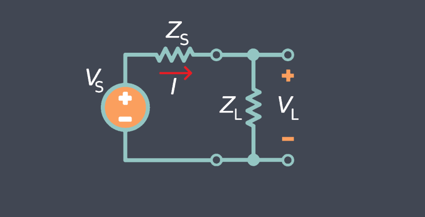
Input impedance refers to the resistance of the sensor to the flow of current from the input signal source. It is a critical parameter that determines the compatibility between the sensor and the signal source, such as a data acquisition system or a control circuit. Input impedance is typically characterized by resistance and reactance.
Sensor input impedance refers to the electrical impedance presented by the input circuitry of a sensor. It represents the opposition to the flow of alternating current (AC) signals into the sensor’s input terminals. The input impedance plays a crucial role in determining the performance and compatibility of the sensor with the connected measurement or control system.
A high input impedance sensor minimizes the current drawn from the signal source, ensuring minimal loading effects and maintaining the accuracy of the input signal. This is particularly important when the signal source has a high output impedance or when multiple sensors need to be connected in parallel to the same signal source.
Few key points about sensor input impedance
Here we prepared a summery of a few key points about sensor input impedance:
Impedance Types
The input impedance of a sensor can be characterized by its magnitude and phase. It typically consists of resistance (R) and reactance (X), where reactance can be inductive (X_L) or capacitive (X_C). In some cases, the input impedance may be purely resistive.
Resistive Impedance:
A resistive input impedance consists solely of resistance (R) and doesn’t
have any reactive components. It means that the impedance is purely resistive and does not introduce phase shifts or frequency-dependent behavior.
Inductive Impedance:
An inductive input impedance contains both resistance (R) and inductive
reactance (X_L). Inductive reactance arises from the presence of inductors in the sensor’s input circuitry. It causes a phase shift between the voltage and current, with the magnitude of reactance increasing with frequency.
Capacitive Impedance:
A capacitive input impedance includes both resistance and capacitive
reactance (X_C). Capacitive reactance is a result of capacitors in the sensor’s input circuitry. It also introduces a phase shift, but in the opposite direction compared to inductive reactance, with the magnitude of reactance decreasing with frequency.
Complex Impedance:
Complex impedance refers to an input impedance that has both
resistive and reactive components. It can include a combination of resistance, inductive reactance, and capacitive reactance. The complex impedance is described by its magnitude and phase angle, which determine the impedance’s behavior across different frequencies.
Impedance Magnitude
The magnitude of the input impedance determines how much current is drawn from the source connected to the sensor.
The magnitude of a sensor’s input impedance refers to the absolute value or magnitude of the impedance, without considering its phase or frequency-dependent behavior. It represents the amount of opposition that the sensor’s input circuitry presents to the flow of alternating current (AC) signals. A higher impedance magnitude results in lower current flow, while a lower impedance magnitude allows for higher current flow.
The input impedance magnitude is typically expressed in ohms (Ω) and can vary widely depending on the type of sensor and its specific design. The magnitude of the input impedance can have important implications for signal integrity, power transfer, and compatibility with the connected measurement or control system.
High Impedance Magnitude:
A sensor with a high input impedance magnitude draws minimal
current from the source connected to its input terminals. High input impedance is desirable in many cases as it minimizes the loading effect on the source, effectively preserving the signal integrity and accuracy.
Low Impedance Magnitude:
A sensor with a low input impedance magnitude draws relatively
higher current from the source. Low input impedance is often preferred in applications where the source has limited current driving capability. It ensures sufficient power transfer to the sensor and helps reduce the impact of noise or interference.
Matching Impedance
In some cases, it may be necessary to match the input impedance of the sensor with the impedance of the connected circuit or instrument. Sensor matching impedance refers to the process of matching the input impedance of a sensor with the impedance of the connected measurement or control system. The goal of impedance matching is to optimize power transfer, minimize signal reflections, and ensure accurate signal transmission between the sensor and the system.
Mismatched impedance can lead to signal degradation, such as attenuation, reflections, or distortion, which can impact the accuracy and reliability of the system.
Source Impedance and Load Impedance:
Impedance matching involves considering both the
source impedance and the load impedance. The source impedance refers to the output impedance of the device or circuit driving the sensor, while the load impedance refers to the input impedance of the sensor. Matching the source impedance and load impedance helps ensure optimal power transfer and signal integrity.
Reflections and Standing Waves:
When the source impedance and load impedance are
mismatched, it can result in signal reflections at the interface between the source and the sensor. These reflections can cause standing waves, leading to signal distortion and reduced measurement accuracy.
Techniques for Impedance Matching:
Various techniques can be employed to achieve
impedance matching, such as using impedance matching networks, transformers, or adjustable components like resistors, capacitors, and inductors. These techniques allow for adjusting the impedance to achieve optimal matching between the source and the sensor.
Signal Integrity
The input impedance affects the signal integrity by interacting with the source impedance of the connected system. A mismatch between the sensor’s input impedance and the source impedance can cause signal degradation, such as attenuation, reflections, and distortion.
Loading Effects
The input impedance of a sensor can affect the source that is driving the sensor. If the sensor’s input impedance is significantly lower than the source impedance, it can cause loading effects, resulting in a change in the source’s output characteristics.
The specific input impedance requirements of a sensor can vary depending on the sensor type, technology, and intended application. It is recommended to consult the sensor datasheet or manufacturer’s specifications for detailed information on the input impedance characteristics of a particular sensor.

