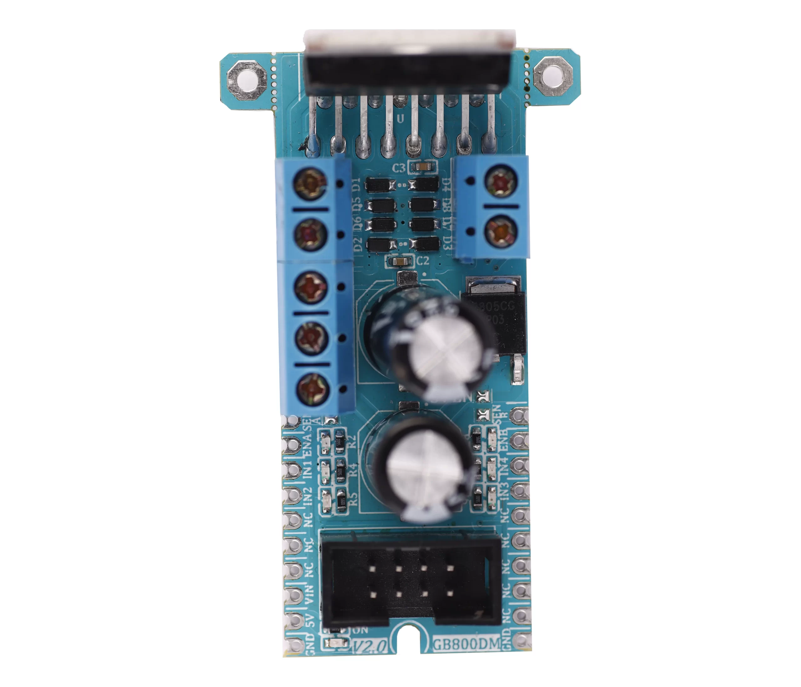
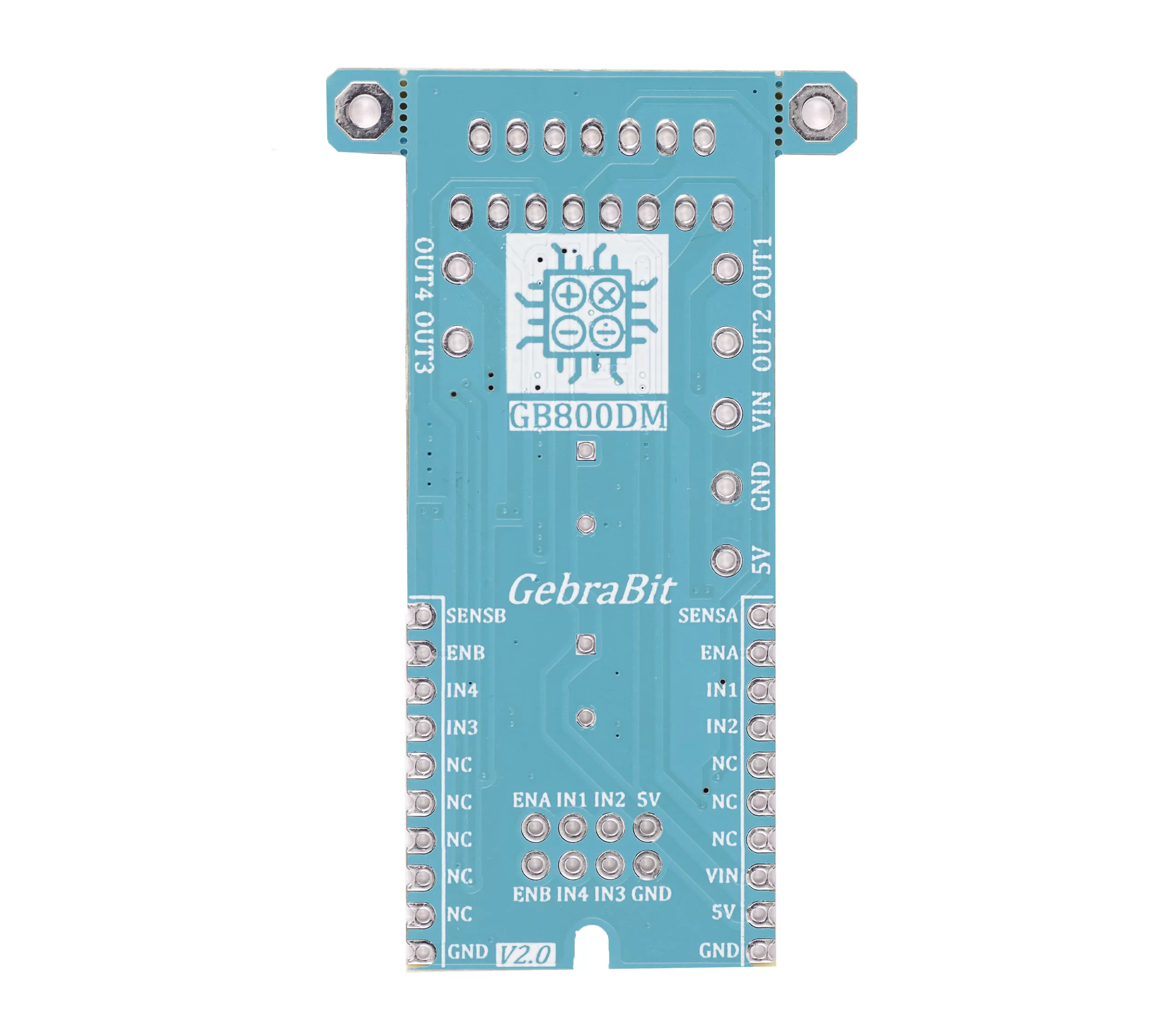
OVERVIEW
Gebrabit L298N is a 4A, up to 35V dual channel motor driver module.
GebraBit L298N needs two separate power supplies for the internal circuitry and motors.
The internal circuitry operates with a 5V through the “5V” pin or onboard module regulator.
The “VIN” pin gives power to the internal H-Bridge of the IC to drive the motors and the onboard integrated regulator.
Users can connect motors to the GebraBit L298N with voltages between 5 to 35V with a peak current up to 2A.
The onboard regulator output will be enabled only when the “5V EN” jumper has been shorted; then, the internal circuitry will be powered by the voltage regulator, and the “5V” pin can be used as an output.
Note: Must not connect a separate power supply to the “5V” pin when the “5V EN” jumper has been shorted.
Users can access the most important pins of the L298N through the GebraBit L298N module. Pins like “IN1”, “IN2”, “IN3″, “IN4” as direction control pins and “ENA”, and “ENB” can be used as speed control (PWM) pins; “SENSA” and “SENSB” which can user short them to the GND with onboard jumpers or connect to a resistor for current sens functions.
For easy accessibility, GebraBit L298N gives access to the “5V”, “GND”, and “IN1”, “IN2”, “IN3”, “IN4”, “ENA”, ” ENB” pins by a 2×4 pin IDC connector to extend them on other boards.
GebraBit L298N has two screw terminal blocks for “OUT1” to “OUT4” to connecting motors and one terminal block for connecting “VIN”, “GND” and “5V” to the module.
The L298 is an integrated monolithic circuit. It is a high voltage, high current dual full-bridge driver designed to accept standard TTL logic levels and drive inductive loads such as relays, solenoids, DC and stepping motors. Two enable inputs are provided to enable or disable the device independently of the input signals. The emitters of the lower transistors of each bridge are connected together and the corresponding external terminal can be used for the connection of an externalsensing resistor. An additional supply input is provided so that the logic works at a lower voltage.
WARNING: FOR ACCURATE INFORMATION ABOUT ICs ABSOLUTE MAXIMUM RATINGS AND ITS PRECIOUS CHARACTERISTICS RANGES, USERS MUST CERTAINLY REFER TO ICs MANUFACTURE DATASHEET.
Key Features
- On Board, ON/OFF LED indicator
- On Board LED indicator for direction and PWM pins
- On Board 5V regulator
- Control Pin access with IDC connector
- Screw terminal blocks for power and motor connections
- GebraBit Pin Compatible with GEBRABUS
- GebraBit Large package
- It can be used as a daughter board of GebraBit MCU Modules
- Featuring Castellated pad (Assembled as SMD Part)
- Separatable screw parts to reduce the size of the board
Pinout Diagram
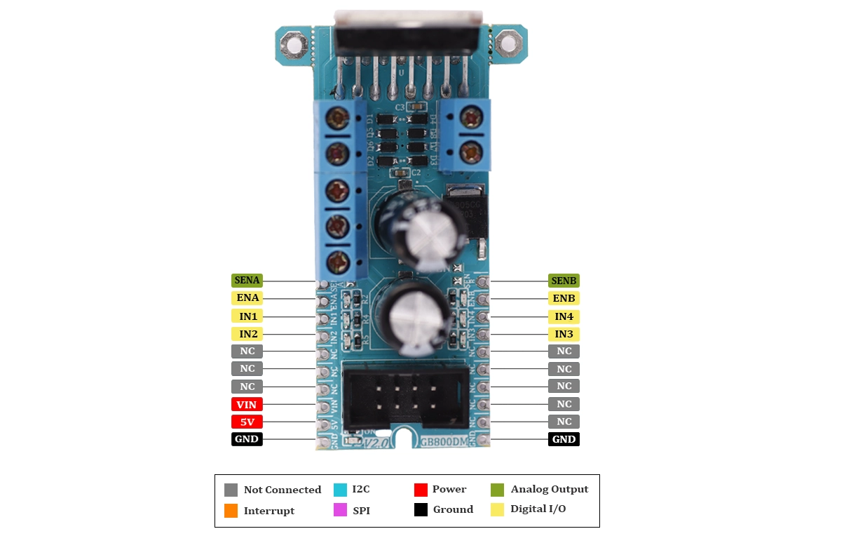
Module Overview
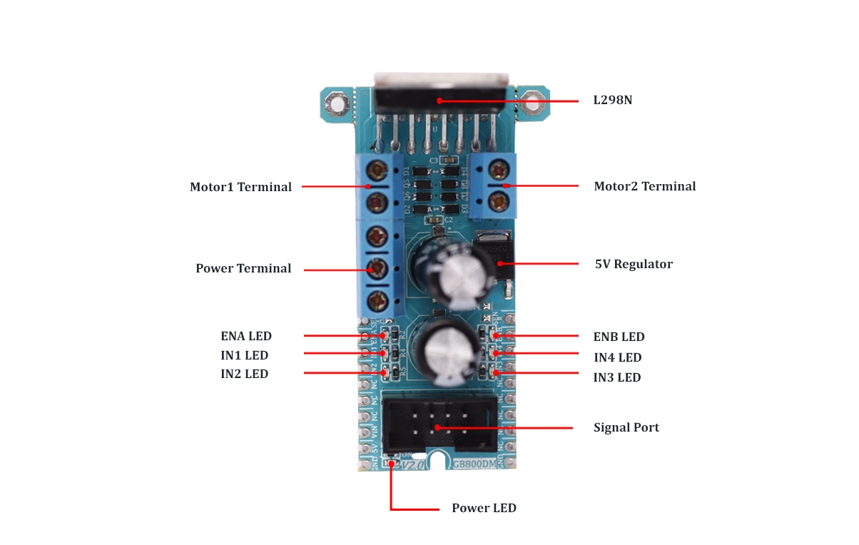
Documents Link
Project and Source Code

Schematic (.Pdf)

Module Layout (.Pdf)

L298N Datasheet

Module Overview

