What's the purpose of this project?
In this section, we are going to launch the HTU20D sensor using ARM microcontroller, STM32F series. In order to use more conveniently and optimally in this project, we use two ready modules GB620EN and GebraBit STM32F303. These two modules contain the minimum necessary elements of the HTU20D sensor and the STM32F microcontroller, which are provided by the GebraBit team to facilitate the work.
What are we going to learn in this tutorial?
In this tutorial, in addition to setting up and using the HTU20D sensor, you will get to know all the HTU20D sensor registers, how to set the various parts of the STM32 microcontroller to set up this sensor using the I2C protocol, how to use the GB620EN module specific library and driver file. You will also learn how to declare functions and finally receive sensor data in the Keil compiler.
What do we need to start this project?
As you probably know, we need some hardware and software to do this project. The titles of these hardware and software are provided to you in the table below and you can prepare/download by clicking on each of them and get ready to start.
|
Required hardware
|
Required software
|
|---|---|
|
Keil compiler
|
|
|
STM32CubeMX program
|
|
|
ST-LINK/V2 programmer
|
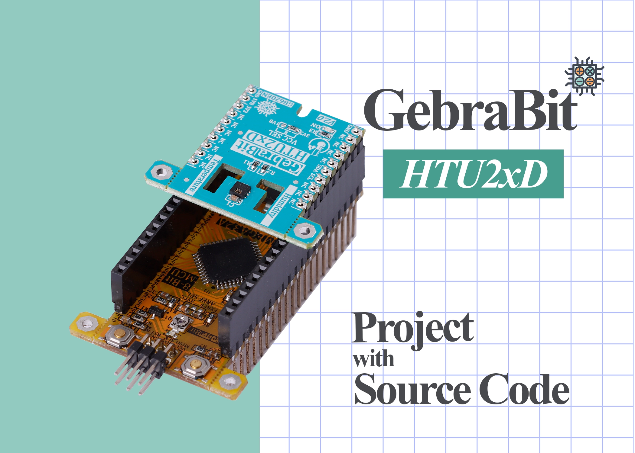
Now, as shown in the image below, we connect the GebraBit HTU20D module to the GebraBit STM32F303 module as follows:

Note: Considering that the PA14 pin of the GebraBit STM32F303 microcontroller module is used to program the microcontroller, the I2C setting on the PA14 and PA15 pins is not possible in this version, so the GebraBit HTU2XD module cannot be placed as a pin to pin on the GebraBit STM32F303 microcontroller module.
Finally, we will see the values of temperature and humidity in Real Time in the “Watch1” window of the Keil compiler in the “Debug Session” mode.
STM32CubeMX settings
In the following, we review the settings related to each of the “I2C”, “RCC”, “Debug”, and “Clock” sections in the STM32F303 microcontroller to develop the GebraBit HTU2XD module.
RCC settings
Due to the presence of “8Mhz” crystal in the GebraBit STM32F303 module, we select the “external clock” in the “RCC” section:
Debug & Programming settings
Regarding the access to “SWCLK” and “SWDIO” pins in the GebraBit STM32F303 module, to reduce the number of pins during “Debug & Programming”, in the “SYS” block, we select the “Serial Wire” option in the “Debug” section:
I2C settings
To communicate with the GebraBit STM32F303 module through I2C, select Standard Mode and select PB8 and PB9 pins as SCL and SDA:
According to the sensor data sheet, the settings of the I2C parameters in the “Parameter Settings” section will be set as shown in the above image.
Clock settings
The “clock” settings for each part of the STM32F303 microcontroller in this code, are as follows:
Project Manager settings
“Project Manager” settings are as follows, here we have used “MDK-ARM” version “5.32” compiler:
After completing all the above settings, we can develop our code easily just by one click on “GENERATE CODE” and adding the HTU2XD library and driver (provided by GebraBit).
You can download the “STM32Cube MX”, “library”, “driver” and KEIL project at the end of this tutorial.
HTU2XD library and driver
In addition to the modular design of various sensors and ICs, GebraBit tries to provide variety of structured and hardware-independent libraries in C language for the ease of users in setting up and developing software.
For this purpose, after preparing each GebraBit module, the users can refer to the “tutorial” section of the desired module and download the dedicated library, which contains the “ .h” and “ .c” file (Header and Source) and a sample training program under “GebraBit STM32F303”, “GebraBit ATMEGA32A” or “Arduino” development boards.
All the defined functions and structures in the library are commented in full detail and all the received parameters in the arguments of the functions and their return values, are briefly explained. Since the libraries are hardware independed, the user can easily add the library in any of their favorite compilers and develop it by desired microcontroller and development board.
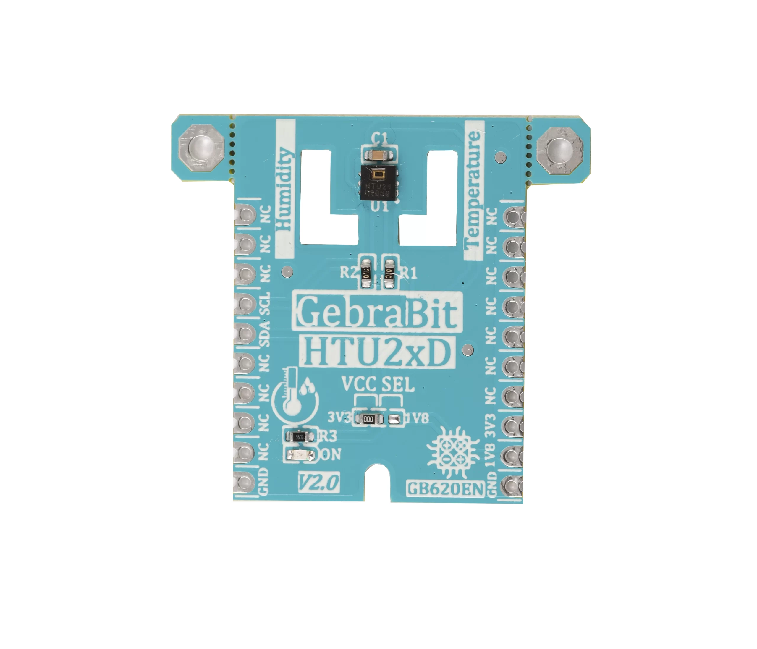
GebraBit HTU2XD.h header file
In this file, based on the datasheet of the sensor or IC, all address registers, the values of each register are defined in the form of “Enumeration”. Also, the casing of the HTU2XD sensor and the configurations related to each of the HTU2XD sensor internal blocks are defined in the form of a “STRUCT” with the name GebraBit_ HTU2XD. Finally, in the Debug Session environment, all the configurations related to each block can be seen in real time.
USER REGISTER MAP
The registry map or sensor commands are defined in this section:
					1. #define HTU2XD_I2C		                             &hi2c1
 2. #define HTU2XD_ADDRESS 								 0x40
 3. #define HTU2XD_WRITE_ADDRESS 			  			 ((HTU2XD_ADDRESS<<1)|0)
 4. #define HTU2XD_READ_ADDRESS 						 ((HTU2XD_ADDRESS<<1)|1)
 5. #define HTU2XD_WRITE_USER_REGISTER_CMD				 0xE6
 6. #define HTU2XD_READ_USER_REGISTER_CMD				 0xE7
 7. #define HTU2XD_RESET_CMD							 0xFE
 8. #define HTU2XD_TRIGGER_TEMPERATURE_MEASUREMENT_CMD	 0xE3  ///Hold Master
 9. #define HTU2XD_TRIGGER_HUMIDITY_MEASUREMENT_CMD		 0xE5  ///Hold Master
10. #define HTU2XD_USER_REGISTER_RESOLUTION_BIT_MASK     0x81
11. // Processing constants
12. #define HTU2XD_TEMPERATURE_COEFFICIENT				 (float)(-0.15)
13. #define HTU2XD_CONSTANT_A							 (float)(8.1332)
14. #define HTU2XD_CONSTANT_B							 (float)(1762.39)
15. #define HTU2XD_CONSTANT_C							 (float)(235.66)
16. // Coefficients for temperature computation
17. #define TEMPERATURE_COEFF_MUL						 (175.72)
18. #define TEMPERATURE_COEFF_ADD						 (-46.85)
19. // Coefficients for relative humidity computation
20. #define HUMIDITY_COEFF_MUL							 (125)
21. #define HUMIDITY_COEFF_ADD							 (-6)
22.
HTU2XD_Ability Enum
The ability to activate or deactivate different parts of the sensor is defined in this enum:
					typedef enum Ability
{
	Disable = 0 ,
	Enable
}HTU2XD_Ability;
HTU2XD_Battery_Status Enum
The values of this enum are used to determine the state of the sensor voltage level:
					1. typedef enum Battery_Status
2. {
3.  HTU2XD_BATTERY_VDD_OK,
4.  HTU2XD_BATTERY_VDD_LOW
5. }HTU2XD_Battery_Status;
6.
HTU2XD_OTP Enum
The values of this enum are used for sensor OTP settings:
					1. typedef enum OTP
2. {
3. 	OTP_DISABLE = 1 ,
4. 	OTP_ENABLE  = 0
5. }HTU2XD_OTP;
6.
HTU2XD_Measurement_Resolution Enum
The values of this enum are used to select the sensor resolution:
					1. typedef enum Measurement_Resolution
2. {
3. 	HTU2XD_HUMIDITY_12BIT_TEMPERATURE_14BIT = 0x00 ,
4. 	HTU2XD_HUMIDITY_8BIT_TEMPERATURE_12BIT  = 0x01 ,
5. 	HTU2XD_HUMIDITY_10BIT_TEMPERATURE_13BIT = 0x80 ,
6. 	HTU2XD_HUMIDITY_11BIT_TEMPERATURE_11BIT = 0x81
7. }HTU2XD_Measurement_Resolution;
8.
HTU2XD_Humidity_Conversion_Time Enum
The values of this enum are used to select the conversion time of humidity values:
					typedef enum Humidity_Conversion_Time
{
	HUMIDITY_12BIT_MEASUREMENT_TIME = 16,
	HUMIDITY_11BIT_MEASUREMENT_TIME = 8 ,
	HUMIDITY_10BIT_MEASUREMENT_TIME = 5 ,
	HUMIDITY_8BIT_MEASUREMENT_TIME  = 3
}HTU2XD_Humidity_Conversion_Time;
HTU2XD_Temperature_Conversion_Time Enum
The values of this enum are used to select the conversion time of temperature values:
					1. typedef enum Temperature_Conversion_Time
2. {
3. 	TEMPERATURE_14BIT_MEASUREMENT_TIME = 50 ,
4. 	TEMPERATURE_13BIT_MEASUREMENT_TIME = 25 ,
5. 	TEMPERATURE_12BIT_MEASUREMENT_TIME = 13 ,
6. 	TEMPERATURE_11BIT_MEASUREMENT_TIME = 7
7. }HTU2XD_Temperature_Conversion_Time;
8.
HTU2XD_CRC_Status Enum
Using this enum, the status of the CRC check is specified:
					1. typedef enum CRC_Status
2. {
3. 	CRC_ERROR = 0,
4. 	CRC_OK
5. }HTU2XD_CRC_Status;
6.
HTU2XD_Reset_Status Enum
By using this enum, the reset status of the sensor is specified:
					1. typedef enum
2. {
3. 	FAILED = 0 ,
4. 	DONE
5. }HTU2XD_Reset_Status;
6.
HTU2XD struct
					1. typedef	struct HTU2XD
 2. {
 3. 	  uint8_t                       	   Register_Cache;
 4. 	  HTU2XD_Reset_Status				   RESET;
 5. 	  HTU2XD_Battery_Status                BATTERY_VDD;
 6. 	  HTU2XD_OTP				           OTP;
 7. 	  HTU2XD_Ability					   ON_CHIP_HEATER;
 8. 	  HTU2XD_Measurement_Resolution        MEASUREMENT_RESOLUTION;
 9. 	  HTU2XD_Humidity_Conversion_Time      HUMIDITY_MEASUREMENT_TIME;
10. 	  HTU2XD_Temperature_Conversion_Time   TEMPERATURE_MEASUREMENT_TIME;
11. 	  uint8_t                              ADC_TEMPERATURE[REGISTER_DATA_BUFFER_SIZE];
12. 	  uint16_t                             ADC_TEMPERATURE_DATA;
13. 	  uint8_t                              ADC_HUMIDITY[REGISTER_DATA_BUFFER_SIZE];
14. 	  uint16_t							   ADC_HUMIDITY_DATA;
15. 	  uint8_t 							   HTU2XD_CRC;
16. 	  HTU2XD_CRC_Status 				   CRC_CHECK;
17.       float 							   TEMPERATURE;
18. 	  float 							   HUMIDITY;
19. 	  float 							   COMPANSATED_HUMIDITY;
20. //	  double							   PARTIAL_PRESSURE;
21. //	  double 							   DEW_POINT;
22. }GebraBit_HTU2XD;
23.
Declaration of functions
At the end of this file, all the functions for reading and writing in HTU2XD registers, sensor configuration and receiving data from the sensor are declared:
					1. /********************************************************
 2.  *  Declare Read&Write HTU2XD Register Values Functions *
 3.  ********************************************************/
 4. extern void GB_HTU2XD_Read_User_Register(uint8_t *data)		;
 5. extern void GB_HTU2XD_Burst_Read(uint8_t regAddr,  uint8_t *data, uint16_t byteQuantity);
 6. extern void GB_HTU2XD_Read_User_Register_Bits ( uint8_t start_bit, uint8_t len, uint8_t* data);
 7. extern void GB_HTU2XD_Write_User_Register(uint8_t data)	;
 8. extern void GB_HTU2XD_Burst_Write(uint8_t regAddr,  uint8_t *data, uint16_t byteQuantity)								;
 9. extern void GB_HTU2XD_Write_User_Register_Bits( uint8_t start_bit, uint8_t len, uint8_t data);
10. /********************************************************
11.  *       Declare MS5611 Configuration Functions         *
12.  ********************************************************/
13. extern void GB_HTU2XD_Soft_Reset ( GebraBit_HTU2XD * HTU2XD )  ;
14. extern void GB_HTU2XD_Check_Battery_Voltage_VDD ( GebraBit_HTU2XD * HTU2XD  ) ;
15. extern void GB_HTU2XD_On_Chip_Heater ( GebraBit_HTU2XD * HTU2XD , HTU2XD_Ability heater )  ;
16. extern void GB_HTU2XD_Read_On_Chip_Heater_Status ( GebraBit_HTU2XD * HTU2XD , HTU2XD_Ability heater )    ;
17. extern void GB_HTU2XD_OTP ( GebraBit_HTU2XD * HTU2XD , HTU2XD_OTP otp )  ;
18. extern void GB_HTU2XD_Read_OTP ( GebraBit_HTU2XD * HTU2XD , HTU2XD_OTP otp ) ;
19. extern void GB_HTU2XD_Measurement_Resolution ( GebraBit_HTU2XD * HTU2XD , HTU2XD_Measurement_Resolution res ) ;
20. extern void GB_HTU2XD_Read_Measurement_Resolution ( GebraBit_HTU2XD * HTU2XD   )   ;
21. extern void GB_HTU2XD_CRC_Check( GebraBit_HTU2XD * HTU2XD , uint16_t value, uint8_t crc)  ;
22. extern void GB_HTU2XD_ADC_Temperature_Raw_Data ( GebraBit_HTU2XD * HTU2XD )  ;
23. extern void GB_HTU2XD_ADC_Humidity_Raw_Data ( GebraBit_HTU2XD * HTU2XD )   ;
24. extern void GB_HTU2XD_initialize( GebraBit_HTU2XD * HTU2XD )  ;
25. extern void GB_HTU2XD_Configuration(GebraBit_HTU2XD * HTU2XD)  ;
26. extern void GB_HTU2XD_Get_Data(GebraBit_HTU2XD * HTU2XD);
27.
GebraBit_ HTU2XD.c source file
In this file, which is written in C language, all the functions are commented in full detail, and all the parameters received in the arguments of the functions and their return values are clearly explained so we confine to these explanations and invite users to check this file directly for more information.
Sample program in Keil
After making the Keil project by STM32CubeMX and adding the “GebraBit_ HTU2XD.c” library provided by GebraBit, we will examine the “main .c” file of the sample tutorial and view the output of the GebraBit_HTU2XD module in the “watch” part in the Keil compiler “Debugging” environment.
Description of “main.c” file
If you look carefully at the beginning part of the “main.c” file, you will notice that the “GebraBit_HTU2XD.h” header has been added to access the GebraBit HTU2XD module required structures, Enums and functions. In the next part, a variable named HTU2XD_Module of the GebraBit_HTU2XD structure type (this structure is in the GebraBit_HTU2XD header and is explained in the GebraBit_HTU2XD library description section) is defined for the configuration of the GebraBit HTU2XD module:
					/* Private typedef -----------------------------------------------------------*/
/* USER CODE BEGIN PTD */
GebraBit_HTU2XD HTU2XD_Module;
/* USER CODE END PTD */
In the next part of the written code, using the GB_HTU2XD_initialize (&HTU2XD_Module) and GB_HTU2XD_Configuration (&HTU2XD_Module) functions, we set the GebraBit HTU2XD module and finally, in the while part of the program, the data is read from the sensor and the humidity and temperature values are continuously received:
					1. /* USER CODE BEGIN 2 */
 2. 	GB_HTU2XD_initialize(&HTU2XD_Module);
 3. 	GB_HTU2XD_Configuration(&HTU2XD_Module);
 4.   /* USER CODE END 2 */
 5.
 6.   /* Infinite loop */
 7.   /* USER CODE BEGIN WHILE */
 8.   while (1)
 9.   {
10.     /* USER CODE END WHILE */
11.
12.     /* USER CODE BEGIN 3 */
13. 	 GB_HTU2XD_Get_Data(&HTU2XD_Module);
14.   }
15.   /* USER CODE END 3 */
16. }
17.
The “main.c” file code text:
					  1. /* USER CODE BEGIN Header */
  2. /*
  3.  * ________________________________________________________________________________________________________
  4.  * Copyright (c) 2020 GebraBit Inc. All rights reserved.
  5.  *
  6.  * This software, related documentation and any modifications thereto (collectively “Software”) is subject
  7.  * to GebraBit and its licensors' intellectual property rights under U.S. and international copyright
  8.  * and other intellectual property rights laws.
  9.  *
 10.  * GebraBit and its licensors retain all intellectual property and proprietary rights in and to the Software
 11.  * and any use, reproduction, disclosure or distribution of the Software without an express license agreement
 12.  * from GebraBit is strictly prohibited.
 13.
 14.  * THE SOFTWARE IS PROVIDED "AS IS", WITHOUT WARRANTY OF ANY KIND, EXPRESS OR IMPLIED, INCLUDING BUT
 15.  * NOT LIMITED TO THE WARRANTIES OF MERCHANTABILITY, FITNESS FOR A PARTICULAR PURPOSE AND NON-INFRINGEMENT IN
 16.  * NO EVENT SHALL GebraBit BE LIABLE FOR ANY DIRECT, SPECIAL, INDIRECT, INCIDENTAL, OR CONSEQUENTIAL DAMAGES,
 17.  * OR ANY DAMAGES WHATSOEVER RESULTING FROM LOSS OF USE, DATA OR PROFITS, WHETHER IN AN ACTION OF CONTRACT,
 18.  * NEGLIGENCE OR OTHER TORTIOUS ACTION, ARISING OUT OF OR IN CONNECTION WITH THE USE OR PERFORMANCE
 19.  * OF THE SOFTWARE.
 20.  * ________________________________________________________________________________________________________
 21.  */
 22. /**
 23.   ******************************************************************************
 24.   * @file           : main.c
 25.   * @brief          : Main program body
 26. 	* @Author       	: Mehrdad Zeinali
 27.   ******************************************************************************
 28.   * @attention
 29.   *
 30.   * Copyright (c) 2022 STMicroelectronics.
 31.   * All rights reserved.
 32.   *
 33.   * This software is licensed under terms that can be found in the LICENSE file
 34.   * in the root directory of this software component.
 35.   * If no LICENSE file comes with this software, it is provided AS-IS.
 36.   *
 37.   ******************************************************************************
 38.   */
 39. /* USER CODE END Header */
 40. /* Includes ------------------------------------------------------------------*/
 41. #include "main.h"
 42. #include "i2c.h"
 43. #include "gpio.h"
 44.
 45. /* Private includes ----------------------------------------------------------*/
 46. /* USER CODE BEGIN Includes */
 47. #include "GebraBit_HTU2XD.h"
 48. /* USER CODE END Includes */
 49.
 50. /* Private typedef -----------------------------------------------------------*/
 51. /* USER CODE BEGIN PTD */
 52. GebraBit_HTU2XD HTU2XD_Module;
 53. /* USER CODE END PTD */
 54.
 55. /* Private define ------------------------------------------------------------*/
 56. /* USER CODE BEGIN PD */
 57. /* USER CODE END PD */
 58.
 59. /* Private macro -------------------------------------------------------------*/
 60. /* USER CODE BEGIN PM */
 61.
 62. /* USER CODE END PM */
 63.
 64. /* Private variables ---------------------------------------------------------*/
 65.
 66. /* USER CODE BEGIN PV */
 67.
 68. /* USER CODE END PV */
 69.
 70. /* Private function prototypes -----------------------------------------------*/
 71. void SystemClock_Config(void);
 72. /* USER CODE BEGIN PFP */
 73.
 74. /* USER CODE END PFP */
 75.
 76. /* Private user code ---------------------------------------------------------*/
 77. /* USER CODE BEGIN 0 */
 78.
 79. /* USER CODE END 0 */
 80.
 81. /**
 82.   * @brief  The application entry point.
 83.   * @retval int
 84.   */
 85. int main(void)
 86. {
 87.   /* USER CODE BEGIN 1 */
 88.
 89.   /* USER CODE END 1 */
 90.
 91.   /* MCU Configuration--------------------------------------------------------*/
 92.
 93.   /* Reset of all peripherals, Initializes the Flash interface and the Systick. */
 94.   HAL_Init();
 95.
 96.   /* USER CODE BEGIN Init */
 97.
 98.   /* USER CODE END Init */
 99.
100.   /* Configure the system clock */
101.   SystemClock_Config();
102.
103.   /* USER CODE BEGIN SysInit */
104.
105.   /* USER CODE END SysInit */
106.
107.   /* Initialize all configured peripherals */
108.   MX_GPIO_Init();
109.   MX_I2C1_Init();
110.   /* USER CODE BEGIN 2 */
111. 	GB_HTU2XD_initialize(&HTU2XD_Module);
112. 	GB_HTU2XD_Configuration(&HTU2XD_Module);
113.   /* USER CODE END 2 */
114.
115.   /* Infinite loop */
116.   /* USER CODE BEGIN WHILE */
117.   while (1)
118.   {
119.     /* USER CODE END WHILE */
120.
121.     /* USER CODE BEGIN 3 */
122. 		GB_HTU2XD_Get_Data(&HTU2XD_Module);
123.   }
124.   /* USER CODE END 3 */
125. }
126.
127. /**
128.   * @brief System Clock Configuration
129.   * @retval None
130.   */
131. void SystemClock_Config(void)
132. {
133.   RCC_OscInitTypeDef RCC_OscInitStruct = {0};
134.   RCC_ClkInitTypeDef RCC_ClkInitStruct = {0};
135.   RCC_PeriphCLKInitTypeDef PeriphClkInit = {0};
136.
137.   /** Initializes the RCC Oscillators according to the specified parameters
138.   * in the RCC_OscInitTypeDef structure.
139.   */
140.   RCC_OscInitStruct.OscillatorType = RCC_OSCILLATORTYPE_HSE;
141.   RCC_OscInitStruct.HSEState = RCC_HSE_ON;
142.   RCC_OscInitStruct.HSEPredivValue = RCC_HSE_PREDIV_DIV1;
143.   RCC_OscInitStruct.HSIState = RCC_HSI_ON;
144.   RCC_OscInitStruct.PLL.PLLState = RCC_PLL_ON;
145.   RCC_OscInitStruct.PLL.PLLSource = RCC_PLLSOURCE_HSE;
146.   RCC_OscInitStruct.PLL.PLLMUL = RCC_PLL_MUL9;
147.   if (HAL_RCC_OscConfig(&RCC_OscInitStruct) != HAL_OK)
148.   {
149.     Error_Handler();
150.   }
151.
152.   /** Initializes the CPU, AHB and APB buses clocks
153.   */
154.   RCC_ClkInitStruct.ClockType = RCC_CLOCKTYPE_HCLK|RCC_CLOCKTYPE_SYSCLK
155.                               |RCC_CLOCKTYPE_PCLK1|RCC_CLOCKTYPE_PCLK2;
156.   RCC_ClkInitStruct.SYSCLKSource = RCC_SYSCLKSOURCE_PLLCLK;
157.   RCC_ClkInitStruct.AHBCLKDivider = RCC_SYSCLK_DIV1;
158.   RCC_ClkInitStruct.APB1CLKDivider = RCC_HCLK_DIV2;
159.   RCC_ClkInitStruct.APB2CLKDivider = RCC_HCLK_DIV1;
160.
161.   if (HAL_RCC_ClockConfig(&RCC_ClkInitStruct, FLASH_LATENCY_2) != HAL_OK)
162.   {
163.     Error_Handler();
164.   }
165.   PeriphClkInit.PeriphClockSelection = RCC_PERIPHCLK_I2C1;
166.   PeriphClkInit.I2c1ClockSelection = RCC_I2C1CLKSOURCE_SYSCLK;
167.   if (HAL_RCCEx_PeriphCLKConfig(&PeriphClkInit) != HAL_OK)
168.   {
169.     Error_Handler();
170.   }
171. }
172.
173. /* USER CODE BEGIN 4 */
174.
175. /* USER CODE END 4 */
176.
177. /**
178.   * @brief  This function is executed in case of error occurrence.
179.   * @retval None
180.   */
181. void Error_Handler(void)
182. {
183.   /* USER CODE BEGIN Error_Handler_Debug */
184.   /* User can add his own implementation to report the HAL error return state */
185.   __disable_irq();
186.   while (1)
187.   {
188.   }
189.   /* USER CODE END Error_Handler_Debug */
190. }
191.
192. #ifdef  USE_FULL_ASSERT
193. /**
194.   * @brief  Reports the name of the source file and the source line number
195.   *         where the assert_param error has occurred.
196.   * @param  file: pointer to the source file name
197.   * @param  line: assert_param error line source number
198.   * @retval None
199.   */
200. void assert_failed(uint8_t *file, uint32_t line)
201. {
202.   /* USER CODE BEGIN 6 */
203.   /* User can add his own implementation to report the file name and line number,
204.      ex: printf("Wrong parameters value: file %s on line %d\r\n", file, line) */
205.   /* USER CODE END 6 */
206. }
207. #endif /* USE_FULL_ASSERT */
208.
Program output
After generating the Keil project using STM32CubeMX and adding the library, we connect the STLINK V2 programmer to the GebraBit STM32F303 using the STLINKV2 adapter:
STLINKV2 adapter:
By connecting the STLINK V2 programmer to the GebraBit STM32F303, there is no need to apply power to the GebraBit STM32F303 and GebraBit HTU2XD modules, because they receive their supply voltage directly from the STLINK V2 programmer.
Finally, enter the “Debug” mode and by adding the “HTU2XD_Module” to the “watch” window and running the program, we can see the changes in the humidity and temperature of the GebraBit HTU2XD module:
In the following, you can download the “GebraBit HTU2XD module setup project” using the GebraBit STM32F303 module in the Keil environment, the “STM32CubeMX file”, the schematic of the modules and the “HTU2XD datasheet”.