GebraBit

GebraBit APDS9306-065 Digital Ambient Light Sensor Module Overview

متن سربرگ خود را وارد کنید

APDS9306 both

GebraBit APDS9306-065 Digital Ambient Light Sensor Module Overview

  1. Home
  2. »
  3. Blog
  4. »
  5. GebraBit APDS9306-065 Digital Ambient Light Sensor Module Overview

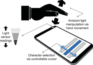
Today, ambient light sensors are part of smartphones, notebooks, other mobile devices, car displays and LCD TVs. These sensors are used to detect the amount of light in the environment, and in devices such as smartphones and notebooks, these sensors are used to automatically adjust the brightness of the display screen, according to the ambient light, as a result, this saves energy and increases the device lifespan.

In general, there are three common types of ambient light sensors: phototransistors, photodiodes, and photonic ICs, which is made of a photodetector and an amplifier.

An overview of the APDS9306-065 sensor

APDS-9306-065 is a low- voltage Digital Ambient Light Sensor that converts light intensity to digital signal output with I2C interface. It consists of photodiode, ADC, oscillator and power-on reset to ensure consistent start-up. ADCs convert the photodiode currents to a digital output. APDS-9306-065 supports programmable hardware interrupt with hysteresis to respond to events.

approximates the response of the human-eye providing direct read out, where the output count is proportional to ambient light level. Low light functionality enables operation behind darkened glass.

Specification

Application

  • Output type: Digital-I2C
  • Wavelength Range: ~420 to ~700nm 
  • Peak Wavelength: 560nm
  • Resolution: 20 Bit
  • Data rate: 125SPS to 8kSPS

For more specifications, please refer to datasheet

  • Detection of ambient light to control display Backlighting (such as Mobile devices–Cell phones, Computing devices–Notebooks, Tablet PC, KeyBoard,etc…)
  • Automatic Residential and Commercial Lighting Management

APDS9306-065 module Key Features

  • User-selectable module power supply voltage between 1V8 and 3V3
  • I2C interface for reading data and configuring the sensor
  • LED indicator for Dedicated Interrupt Pin
  • On Board, ON/OFF LED indicator
  • Pin Compatible with GEBRABUS
  • It can be used as a daughter board of GEBRABIT MCU Modules
  • Featuring Castellated pad (Assembled as SMD Part)
  • Separatable screw parts to reduce the size of the board
  • Package: GebraBit small (36.29mm x 32.72mm)

GebraBit APDS9306-065 module

GebraBit APDS-9306-065 is Digital Ambient Light Sensor that converts light.

GebraBit APDS-9306-065 module can operate with “1V8” or “3V3” supply Voltages by Considered “VDD SEL” jumper selector.

The GebraBit APDS-9306-065 module communicates with the I2C protocol and features a LED indicator for Dedicated Interrupt Pin.

Considering that it is difficult to access the sensor pins, the user needs a starter circuit and driver for the hardware development and of course the software development of the APDS-9306-065 sensor. GebraBit implements the APDS-9306-065 sensor circuit and provides access for the convenience of users.

It is enough to put the GebraBit APDS-9306-065  module in the BreadBoard, then by applying the proper voltage set up the GebraBit APDS-9306-065 module with any of Arduino, Raspberry Pi, Discovery board, and especially we recommend using GebraBit microcontroller development modules (GebraBit STM32F303 or GebraBit ATMEGA32 module) then receive the data.      

The reason for our recommendation when setting up the GebraBit APDS-9306-065 module with GebraBit microcontroller development modules (such as GebraBit STM32F303 or GebraBit ATMEGA32), is the presence of an internal 3V3 regulator on these modules and the compatibility of the pin order of all GebraBit modules together (GEBRABUS standard), it’s enough to Put the APDS-9306-065 in the corresponding socket as shown in the above picture and develop the desired sensor module without the need for wiring.     

Introduction of module sections

APDS9306-065 sensor

APDS9306-065 sensor is the Ambient Light sensor of this module which is placed in the center of the module and its circuit is designed.

VCC SEL

According to the state of 0R resistance of this jumper, the main voltage of the sensor power supply is selected between “1V8” and “3V3”.

Interrupt LED

A dedicated LED is considered for the interrupt pin on the module and its status changes when the interrupt state changes according to the sensor data sheet.

Power supply LED

According to the state of the VCC SEL jumper and applying voltage to the module by the corresponding pin, the LED of the module will be lit.

GebraBit APDS9306-065 Module pins

Supply pins

  • 3V3 and 1V8: These pins can supply the sensor main power supply and the logic level of the sensor digital connection (I2C) according to the state of the VCC SEL selector jumper.
  • GND: This is the common ground pin for power and logic level of the sensor.

I2C pins

  • SDA: This pin is the I2C communication data pin, which is connected to the corresponding data pin in the microcontroller (processor). According to the state of the VCC SEL jumper, you can use the logic level with a voltage of 1V8 or 3V3.
  • SCL: This pin is the I2C communication clock pin, which is connected to the corresponding clock pin in the microcontroller (processor). Depending on the state of the VCC SEL jumper, you can use the logic level with a voltage of 1V8 or 3V3.

Interrupt pin

  • INT : Interrupt pin for APDS9306-065 sensor, according to the datasheet , the user can set the interrupt conditions, the modes and methods of the interruption, etc.

Connect to the processor

I2C connection with GebraBit STM32F303

for i2c communication of GebraBit APDS9306-065 and GebraBit STM32F303 microcontroller module, after defining SDA and SCL on pins PB9 and PB8 (for convenience in STMCUBEMX), follow the below steps:

  • Connect the 3V3 pin of the APDS9306-065 module to the 3V3 output pin of the microcontroller module. (red wire)
  • Connect the GND pin of the APDS9306-065 module to the GND pin of the microcontroller module (black wire).
  • Connect the SCL pin of the APDS9306-065 module to the PB8 pin of the microcontroller (SCL) module (blue wire).
  • Connect the SDA pin of the APDS9306-065 module to the PB9 pin of the microcontroller (SDA) module. (yellow wire)

Note: Considering that the PA14 pin of the GebraBit STM32F303 microcontroller module is used to program the microcontroller, I2C setting on the PA14 and PA15 pins is impossible in this version, so in this version for  I2C  connection with the GebraBit STM32F303 microcontroller module, GebraBit APDS9306-065 module cannot be placed as Pin to Pin on it.

I2C connection with GebraBit ATMEGA32A

Considering that the I2C pins of the ATMEGA32A microcontroller are based on the GEBRABUS standard and correspond to the I2C pins of other GEBRABIT modules, the GebraBit APDS9306-065  module can be placed pin to pin  on the GebraBit ATMEGA32A module Here, for better understanding, the separate connection of these two modules is shown.

Note: If you are using GebraBit microcontroller modules, note that the power selector jumper of the GebraBit APDS9306-065 is set to 3V3 so that you can easily power-on the GebraBit APDS9306-065  module by getting the 3V3 voltage from the microcontroller module.

I2C Connection with ARDUINO UNO

follow the below steps to connect the GebraBit APDS9306-065 module to the ARDUINO UNO via I2C:

  • Since the VCC SEL jumper is set to 3V3, connect the “3V3” pin of the APDS9306-065 module to the “3V3” output pin of the ARDUINO UNO board. (Red wire)
  • Connect the SCL pin of the APDS9306-065 module to the A4 pin of the ARDUINO UNO board (SCL). (orange wire)
  • Connect the SDA pin of the APDS9306-065 module to the A4 pin of the ARDUINO UNO board (SDA). (blue wire)

How to connect the above mentioned steps, can be seen in this picture:

این مقاله را با دوستانتان به اشتراک بگذارید!

Leave a Reply

Your email address will not be published. Required fields are marked *

Shopping cart
Start typing to see posts you are looking for.

Sign in

No account yet?