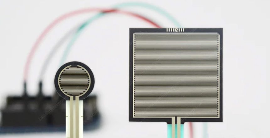
A force sensor measures the force applied to an object or surface. It converts mechanical force into an electrical signal. Types include strain gauge force sensors, piezoelectric force sensors, and capacitive force sensors. Applications include industrial automation, robotics, material testing, and medical devices.
Force sensors are devices used to measure the force or load applied to them. They convert the applied force into an electrical output that can be measured and analyzed.
Most force sensors utilize the strain gauge principle. A strain gauge is a small wire or foil that changes its electrical resistance when subjected to mechanical strain or deformation.
Force sensors are designed to be installed between the load or object being measured and its support structure. They may be integrated into the structure or attached externally. Proper configuration and calibration are crucial for accurate measurements.
Force sensors come in various shapes, sizes, and measurement ranges to suit different applications. They are widely used in industries such as automotive, aerospace, robotics, material testing, medical devices, and industrial automation. Common applications include force measurement, weighing systems, strain analysis, tension and compression testing, and feedback control systems.
It’s important to select the right force sensor based on the specific application requirements, including the expected force range, environmental conditions, accuracy, and compatibility with the data acquisition or control system being used.
Different types of force sensors and how they work
There are several types of force sensors available, each designed to suit different measurement requirements and applications. Here are some commonly used force sensor types:
Strain gauge load cells
Strain gauge load cells are one of the most commonly used force sensor types. They work on the principle of strain gauges, which are devices that change resistance when subjected to strain or deformation.
Strain gauge load cells are typically made up of a metal body or structure that undergoes deformation when a force is applied.
Inside the load cell, one or more strain gauges are attached to the surface that experiences the strain.
When a force is applied to the load cell, it causes the metal body to deform slightly. This deformation results in a change in the electrical resistance of the strain gauge(s).

The strain gauges are connected in a Wheatstone bridge configuration, which is an electrical circuit that measures small changes in resistance. As the applied force causes the resistance of the strain gauge(s) to change, it creates an imbalance in the Wheatstone bridge circuit.

The imbalance in the bridge circuit generates a small electrical signal proportional to the applied force. This signal is then amplified and converted into a usable form, such as voltage or current, by the load cell’s electronics.
Before using a strain gauge load cell, it needs to be calibrated by applying known forces and measuring the corresponding output signals. This calibration process ensures accurate and reliable force measurements.
strain gauge load cells advantages and applications:
Strain gauge load cells are widely used in various applications, including weighing scales, industrial machinery, material testing, aerospace, automotive testing, and more. They offer good accuracy, high resolution, and can measure both tension and compression forces.
It’s worth noting that strain gauge load cells require proper installation and protection from external factors like temperature changes, humidity, and mechanical shocks to ensure accurate and stable performance.
Piezoelectric load cells
Piezoelectric load cells are a type of force sensor that utilize the piezoelectric effect to measure force or pressure. The piezoelectric effect refers to the ability of certain materials to generate an electrical charge in response to mechanical stress or deformation.
Piezoelectric load cells consist of one or more piezoelectric elements, usually made of crystals or ceramics, which are mechanically deformed when a force is applied. These elements are typically mounted within a protective housing.

When a force is applied to the load cell, it deforms the piezoelectric elements, causing a change in their shape. This mechanical deformation generates an electrical charge within the elements.
The generated electrical charge is collected by electrodes attached to the piezoelectric elements. The charge is then converted into a measurable electrical output signal using amplification and conditioning circuits.
Like other load cells, piezoelectric load cells require calibration to establish a relationship between the applied force and the corresponding electrical output signal. Calibration can be done by applying known forces and recording the resulting signals.
Piezoelectric load cells advantages and disadvantages:
Piezoelectric load cells have several advantages, including high accuracy, fast response time, and the ability to measure dynamic forces. They are commonly used in applications such as material testing, impact measurements, compression testing, force monitoring, and vibration analysis.
Piezoelectric load cells may also have limitations when it comes to long-term stability and sensitivity to temperature changes. Therefore, proper environmental conditions and regular recalibration may be necessary to maintain accurate and reliable measurements.
Capacitive load cells
Capacitive load cells are another type of force sensor commonly used to measure force or weight. They operate based on the principle of changes in capacitance due to applied force.
Capacitive load cells consist of two parallel plates separated by a small gap. When a force is applied to the load cell, it causes a change in the gap between the plates, thereby changing the capacitance.

The applied force causes a deformation in the load cell, which results in a change in the overlapping area and the distance between the plates. This change in geometry leads to a change in the capacitance of the load cell.
The change in capacitance is measured using electronic circuits that detect the difference in charge stored between the plates. This change is then converted into an electrical output signal, usually voltage or current, proportional to the applied force.
Just like other load cells, capacitive load cells require calibration to establish a relationship between the applied force and the corresponding electrical output signal. Calibration usually involves applying known forces and recording the resulting signals.
Capacitive load cells advantages and disadvantages:
Capacitive load cells offer benefits such as high accuracy, stability, and resistance to electromagnetic interference. They are commonly used in various applications, including weighing systems, industrial automation, medical devices, and force monitoring tasks.
It is important to ensure proper installation and avoid excessive loading or overloading that could cause mechanical damage to the load cell. Additionally, periodic calibration and maintenance are essential for maintaining accurate and reliable measurements over time.

