

These sensors detect and measure magnetic fields, and are commonly used in navigation, robotics, and industrial automation.
Magnetic sensors are devices that detect and measure magnetic fields. They work based on the principles of magnetism and the interaction between magnetic fields and certain materials. These sensors convert the changes in the magnetic field into electronic signals. The most basic examples of magnetic fields are the Earth’s magnetic field and the magnetic field of a magnet. Magnetic sensors actually convert the “magnitude of these magnetic fields”, which are invisible into “visible electrical signals”.
There are various types of magnetic sensors, including Hall effect sensors, magnetoresistive sensors, and fluxgate sensors.
Hall Effect Sensors
The hall effect sensor is one type of magnetic sensor types which can be used for detecting the strength and direction of a magnetic field. To do so, these sensors utilize the Hall effect, which is the production of a voltage difference across an electrical conductor when it is subjected to a magnetic field perpendicular to the current flow.
In 1879, scientist Edwin Hall discovered that if a magnet is placed perpendicular to a conductor with a steady flow of current, the electrons flowing within the conductor are pulled to one side, thus creating a potential difference in charge (i.e. voltage). The Hall effect, then, is indicative of the presence and magnitude of a magnetic field near a conductor. Hall effect sensors typically consist of a semiconductor material with a current-carrying conductor and a transverse magnetic field. As the magnetic field changes, it induces a voltage across the conductor, which can be measured to determine the strength and direction of the magnetic field.
When a magnetic field is applied perpendicular to the current flow, it causes the free charge carriers (electrons or holes) in the semiconductor material to deflect due to the Lorentz force (In the following we gonna talk about it briefly).
This deflection creates a voltage difference, known as the Hall voltage, across the current-carrying conductor.
By measuring this Hall voltage, the strength and direction of the magnetic field can be determined.
The name of this law is derived from the name of the Dutch physicist Hendrik Lorentz who first described this force. According to this, The Lorentz force is the force experienced by a charged particle moving through a magnetic field.
The Lorentz force (F) acting on a charged particle with charge q moving with velocity v in a magnetic field B can be calculated using the following equation:
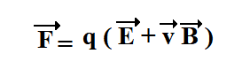
where
- F is the electromagnetic force on a test charge
- q is the particle’s electric charge
- v is the velocity
- E refers to the external electric field
- B is the magnetic field
Hall effect sensors are used to detect variables such as the proximity, speed, or displacement of a mechanical system. One of the Hall effect sensors advantages is that they do not require any contact. They do not have to come in contact with a physical element. They can produce either a digital (on and off) or analog (continuous) signal depending on their design and intended function.
Magnetoresistive Sensors
Magnetoresistive sensors are based on the property of materials called magnetoresistance, which is the change in electrical resistance in response to a magnetic field. There are two common types of magnetoresistive sensors: giant magnetoresistive (GMR) and anisotropic magnetoresistive (AMR) sensors. These sensors use thin layers of magnetic and non-magnetic materials, and as the magnetic field changes, the resistance of the sensor changes. This change in resistance is measured, usually using a Wheatstone bridge circuit, to determine the strength and direction of the magnetic field.
Giant magnetoresistive (GMR) sensor
GMR sensors are based on the discovery of the GMR effect, which was first observed in 1988 by Albert Fert and Peter Grünberg. The GMR effect occurs in certain multilayer thin-film structures composed of alternating ferromagnetic and non-magnetic layers. When a magnetic field is applied perpendicular to the layers, the electrical resistance of the structure changes.
In a GMR sensor, a stack of these ferromagnetic and non-magnetic layers is fabricated into a small device. When an external magnetic field is applied, it causes the magnetization of the ferromagnetic layers to align or rotate, affecting the electrical resistance of the device.
The magnetization of each ferromagnetic layer is exposed to the spin-dependent scattering of electrons as they pass through the middle layer.
If the spin direction of electrons passing through the ferromagnetic layer is opposite that of the magnetization of the ferromagnetic material, the interaction effect is much weaker than when the direction of spin is parallel to magnetization.
As a result, when the direction of magnetization of the upper and lower ferromagnetic material is parallel, resistance to the current flowing along the boundary surface of the conductive material drops, while it increases if the direction of magnetization is anti-parallel.
This change in resistance can be measured, allowing the detection and quantification of the magnetic field.
Parallel magnetization direction → low resistance
Antiparallel magnetization direction → High resistance
GMR sensors are highly sensitive, offering better performance than traditional magnetic sensors. They can detect even weak magnetic fields and provide a wide dynamic range. Due to their small size and low power consumption, GMR sensors have found applications in various fields, including magnetic read heads in hard disk drives, magnetic field sensors in automotive applications, compasses in electronic devices, and proximity and position sensors, among others.
Anisotropic magnetoresistive (AMR) sensors
Anisotropic Magnetoresistive (AMR) sensors are another type of magnetic sensor that utilizes the anisotropic magnetoresistance effect to detect and measure magnetic fields. Similar to Giant Magnetoresistive (GMR) sensors, AMR sensors are widely used in various applications.
The AMR effect is based on the change in resistance of a material when subjected to an external magnetic field. In an AMR sensor, a thin film with anisotropic electrical resistance is constructed from ferromagnetic materials such as nickel-iron alloys. The resistance of this film changes in response to the orientation of the magnetic field applied to it.
When there is no magnetic field, the resistance of the AMR sensor is highest. When the magnetization direction in a ferromagnetic material is parallel to the current, the electron orbital becomes perpendicular to the current, which maximizes resistance. This increases the spin-dependent scattering causing electric resistance to rise.
When the magnetization direction is perpendicular to the current, the electron orbital becomes horizontal to the current reducing the spin-dependent scattering, which minimizes resistance.
Perpendicular magnetization direction → low resistance
Parallel magnetization direction → High resistance
AMR sensors are known for their high sensitivity and low power consumption. They can detect and measure both weak and strong magnetic fields accurately. Moreover, AMR sensors have a wide linear range and can operate over a broad temperature range.
These characteristics make AMR sensors suitable for various applications. They are commonly used in compasses, position and speed sensing applications, non-destructive testing, automotive navigation systems, and magnetic field detection in medical devices.
Fluxgate Sensors
Fluxgate sensors operate based on the principle of magnetic fluxgate or magnetic hysteresis loop. These sensors typically consist of a ferromagnetic core surrounded by coils of wire. When an alternating current is applied to the coils, it causes the core’s magnetic field to constantly reverse. Any external magnetic field near the sensor will cause a distortion in the core’s field, resulting in a secondary signal that can be measured. By analyzing this secondary signal, the strength and direction of the external magnetic field can be determined.