GebraBit

GebraBit MQ7 CO Gas Sensor Module Overview

متن سربرگ خود را وارد کنید

MQ7 both

GebraBit MQ7 CO Gas Sensor Module Overview

  1. Home
  2. »
  3. Blog
  4. »
  5. GebraBit MQ7 CO Gas Sensor Module Overview

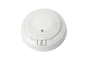
A carbon monoxide detector or CO detector is a device that detects the presence of the carbon monoxide (CO) gas to prevent carbon monoxide poisoning. CO detectors are designed to measure CO levels over time and sound an alarm before dangerous levels of CO accumulate in an environment, giving people adequate warning to safely ventilate the area or evacuate.

An overview of the MQ7 sensor

The gas sensing material used in the MQ-7 gas sensor is tin dioxide (SnO2), which has low conductivity in clean air. When carbon monoxide gas exists in the environment where the sensor is located, the conductivity of the sensor increases with the increase of carbon monoxide gas concentration in the air. This sensor features Fast response and recovery and Adjustable sensitivity.

Specification

Application

  • Output Type: Analog-Voltage/Digital-Logic
  • Detection Range: 10 to 10000 ppm

For more specifications, please refer to datasheet

  • For more specifications, please refer to datasheet

MQ7 module Key Features

  • On Board, ON/OFF LED indicator
  • On Board LED indicator for Digital Comparator Output
  • GEBRABIT Pin Compatible with GEBRABUS
  • It can be used as a daughter board of GEBRABIT MCU Modules
  • Featuring Castellated pad (Assembled as SMD Part)
  • Separatable screw parts to reduce the size of the board
  • Package: GebraBit medium (36.29mm x 46.18mm)

GebraBit MQ7 module

Gebrabit MQ7 is a Semiconductor Carbon Monoxide measurement module. This module is a Low Power-Consumption CO Module which operates just with an input “5V” supply Voltage. GebraBit MQ7 module amplifies MQ7 sensor output by an integrated op-amp circuit for better analysis and interpretation and provides it on the module “AO” pin. For reading CO data, just connect the analog “AO” pin to MCU ADC and go on. Two potentiometers are installed on the GebraBit MQ7 module to determine the sensitivity of the measurement and the threshold value of the gas intensity.

Users need a starter circuit and driver for hardware development and of course software development of the MQ7 sensor. GebraBit has done this by implementing the MQ7 sensor circuit and provided access to its output for users.

It is enough to put the GebraBit MQ7 module in the BreadBoard, then by applying the proper voltage set up the GebraBit MQ7 module with any of Arduino, Raspberry Pi, Discovery board, and especially we recommend using GebraBit microcontroller development modules (GebraBit STM32F303 or GebraBit ATMEGA32 module) then receive the data.       

The reason for our recommendation when setting up the GebraBit MQ7 module with GebraBit microcontroller development modules (such as GebraBit STM32F303 or GebraBit ATMEGA32), is the compatibility of the pin order of all GebraBit modules together (GEBRABUS standard), it’s enough to Put the MQ7 in the corresponding socket as shown in the above picture and develop the desired sensor module without the need for wiring.  

Introduction of module sections

MQ7 sensor

The MQ7 sensor is the main IC of this module, which is responsible for detecting carbon monoxide gas and is placed on top of the module and its circuit is designed.

Amplifire

An amplifier is installed on the GebraBit MQ7 module to amplify the output of the MQ7 sensor for better data analysis.

Sensitivity potentiometer

In designing the MQ7 sensor circuit, a potentiometer is used to determine the module sensitivity. This potentiometer is located on the right side of the module.

Intensity threshold potentiometer

In the circuit design of the MQ7 sensor, in addition to the sensitivity level, the sensitivity threshold of the sensor can be adjusted too. For this purpose, another potentiometer is installed on the left side of the module to determine the sensitivity threshold of the sensor.

Dout LED

When the Gas intensity goes above, or below the threshold, the “Dout” LED status will be changed.

Power LED

By applying voltage to the module through the Power pin, this LED is lit.

GebraBit MQ7 Module pins

Supply pins

  • 5V: This pin supplies the sensor main power supply.
  • GND: This is the ground pin for powering the sensor.

Output pins

  • AO: This pin is used to receive the analog output of the module. To read the sensor output data, it is enough to connect this pin to the ADC of the microcontroller.
  • DO: This pin is used to receive the digital output of the module and when the gas intensity is higher or lower than the set threshold, the logic output (0 and 1) also changes.

Connect to the processor

Connection with GebraBit STM32F303

Due to the compatibility of the pin order of GebraBit modules with each other (GEBRABUS standard), to start the GebraBit MQ7 module with GebraBit STM32F303 microcontroller module, it is enough to easily place the GebraBit MQ7 module as pin to pin on the GebraBit STM32F303 module and start the module by applying voltage. Here, for better understanding, the separate connection of these two modules is shown:

Connection with GebraBit ATMEGA32A

Due to the compatibility of the pin order of GebraBit modules with each other (GEBRABUS standard), to start the GebraBit MQ7 module with the GebraBit ATMEGA32A microcontroller module, it is enough to easily place the GebraBit MQ7 module as pin to pin on the GebraBit ATMEGA32A module and start the module by applying voltage. Here, for better understanding, the separate connection of these two modules is shown:

Connection with ARDUINO UNO

Follow the steps below to connect the GebraBit MQ7 module to ARDUINO UNO:

  • Connect the “5V” pin of the MQ7 module to the “5V” pin of the ARDUINO UNO board output (red wire).
  • Connect the “GND” pin of the MQ7 module to the “GND” pin of the ARDUINO UNO board. (Black wire)
  • Connect the “DO” pin of the MQ7 module to one of the ARDUINO UNO board digital pins (blue wire).
  • Connect the “AO” pin of the MQ7 module to one of the ARDUINO UNO board analog pins (orange wire).

How to connect the above mentioned steps can be seen in this picture:

این مقاله را با دوستانتان به اشتراک بگذارید!

Leave a Reply

Your email address will not be published. Required fields are marked *

Shopping cart
Start typing to see posts you are looking for.

Sign in

No account yet?