GebraBit

GebraBit UVA Sensor Module Overview

متن سربرگ خود را وارد کنید

UVA both side

GebraBit UVA Sensor Module Overview

  1. Home
  2. »
  3. Blog
  4. »
  5. GebraBit UVA Sensor Module Overview

UV sensors measure the power or intensity of incident ultraviolet (UV) radiation. This form of electromagnetic radiation has shorter wavelengths than visible radiation, but is still longer than x-rays. UV sensors are used for determining exposure to ultraviolet radiation in laboratory or environmental settings. They are transmitters that respond to one type of energy signal by producing energy signals of a different type. Generally, these output signals are electrical signals that are routed directly to an electrical meter for observation and recording. The generated electrical signals from UV sensors can also be sent to an analog-to-digital converter (ADC), and then to a computer with software for generating graphs and reports.

UV sensors are used in many different applications. Examples include pharmaceuticals, automobiles, and robotics. UV sensors are also used in the printing industry for solvent handling and dyeing processes. In addition, UV sensors are also used in the chemical industry for the production, storage, and transportation of chemicals.

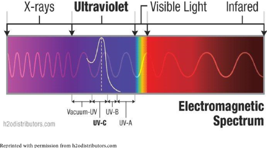
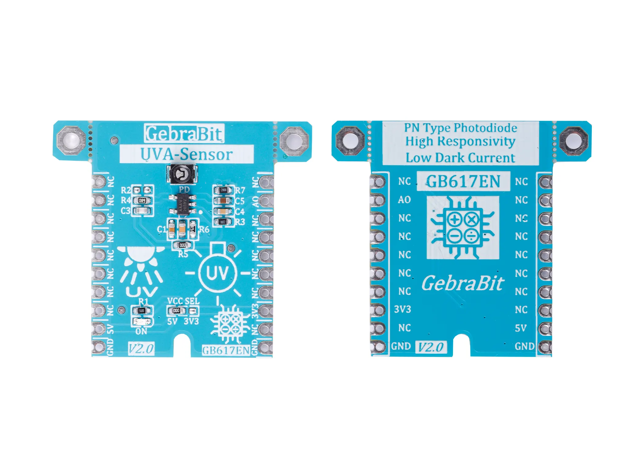
The UVA (Ultra Violet A-rays) sensor is an ultraviolet light sensor that can detect the wavelength range of 320 to 390 nm of UV rays.

An overview of the GVGR-S11SD photodiode

GVRG-S11SD is a PN-type Photodiode working in the spectral range of 295~490 nm and housed into a SMD 3528 package. It’s a great solution, as example for UV curing.

Specification

Application

  • Output Type: Analog-Voltage
  • Wavelength Range: 295 to 490 nm
  • Peak Wavelength: ~360 nm

For more specifications, please refer to datasheet

  • blue LED monitoring
  • UV curing or UV LED monitoring.

UVA Sensor module Key Features

  • User-selectable module power supply voltage between 3V3 and 5V
  • Photovoltaic Mode PN-type Photodiode
  • integrated op-amp
  • On Board, ON/OFF LED indicator
  • Pin Compatible with GEBRABUS
  • It can be used as a daughter board of GEBRABIT MCU Modules
  • Featuring Castellated pad (Assembled as SMD Part)
  • Separatable screw parts to reduce the size of the board
  • Package: GebraBit small (36.29mm x 32.72mm)

GebraBit UVA sensor module

GebraBit UVA-SENSOR  features Photovoltaic Mode PN-type Photodiode.

This module can operate with “3V3” or “5V” supply Voltages by Considered “VCC SEL” jumper selector.

As you know, sensor Output is current type, so GebraBit UVA-SENSOR has an integrated op-amp which converts UV-A Photodiode Output, to an analog voltage on the “A0” pin.

The user needs a starter circuit and driver for the hardware development and of course the software development of the UVA sensor. GebraBit has designed the UVA sensor circuit using an UV-A photodiode and provided access to its analog output for users.  

It is enough to put the GebraBit UVA-SENSOR module in the BreadBoard, then by applying the proper voltage set up the GebraBit UVA-SENSOR module with any of Arduino, Raspberry Pi, Discovery board, and especially we recommend using GebraBit microcontroller development modules (GebraBit STM32F303 or GebraBit ATMEGA32 module) then receive the data.      

The reason for our recommendation when setting up the GebraBit UVA-SENSOR module with GebraBit microcontroller development modules (such as GebraBit STM32F303 or GebraBit ATMEGA32), is the presence of an internal 3V3 regulator on these modules and the compatibility of the pin order of all GebraBit modules together (GEBRABUS standard), it’s enough to Put the UVA-SENSOR in the corresponding socket as shown in the above picture and develop the desired sensor module without the need for wiring.     

Introduction of module sections

GVGR-S11SD photodiode

The GVGR-S11SD photodiode is a PN type photodiode that is used as a UV-A sensor in this module and its circuit is designed and placed on top of the module.

VCC SEL

According to the state of the VCC SEL selector jumper 0R resistance, the main voltage of the sensor power supply is selected between “5V” and “3V3”.

Op amp

There is an integrated op amp on the GebraBit UVA-SENSOR module to convert the sensor current output to analog voltage. This analog voltage output is available to the user on pin “A0”.

Power LED

According to the state of the VCC SEL jumper and applying voltage to the module by the corresponding pin, this LED is lit.

GebraBit UVA sensor Module pins

Supply pins

3V3 and 5V: These pins can supply the sensor main power according to the state of the VCC SEL selector jumper.

GND: This is the ground pin for powering the sensor.

Analog output pin

AO: The sensor output data will be available in the form of analog voltage through this pin, and the output of this pin will change when the ultraviolet light intensity changes.

Connect to the processor

Connection with GebraBit STM32F303

Due to the compatibility of the pin order of GebraBit modules with each other (GEBRABUS standard), to start the GebraBit UVA-SENSOR module with GebraBit STM32F303 microcontroller module, it is enough to easily place the GebraBit UVA-SENSOR module as pin to pin on the GebraBit STM32F303 module and start the module by applying voltage. Here, for better understanding, the separate connection of these two modules is shown:

Connection with GebraBit ATMEGA32A

Due to the compatibility of the pin order of GebraBit modules with each other (GEBRABUS standard), to start the GebraBit UVA-SENSOR module with the GebraBit ATMEGA32A microcontroller module, it is enough to easily place the GebraBit UVA-SENSOR module as pin to pin on the GebraBit ATMEGA32A module and start the module by applying voltage. Here, for better understanding, the separate connection of these two modules is shown:

Note: When using GebraBit microcontroller modules, note that the VCC SEL selector jumper of the GebraBit UVA-SENSOR  module is set to “3V3” so that you can easily get the “3V3” voltage from the microcontroller module.

Connection with ARDUINO UNO

Follow the steps below to connect the GebraBit UVA-SENSOR  module to ARDUINO UNO:

  • Connect the “3V3” pin of the UVA-SENSOR module to the “3V3” pin of the ARDUINO UNO board output (red wire).
  • Connect the “GND” pin of the UVA-SENSOR module to the “GND” pin of the ARDUINO UNO board. (Black wire)
  • Connect the “AO” pin of the UVA-SENSOR  module to one of the ARDUINO UNO board analog pins (blue wire).

How to connect the above mentioned steps can be seen in this picture:

این مقاله را با دوستانتان به اشتراک بگذارید!

Leave a Reply

Your email address will not be published. Required fields are marked *

Shopping cart
Start typing to see posts you are looking for.

Sign in

No account yet?