A carbon dioxide sensor or CO2 sensor is an instrument for the measurement of carbon dioxide gas. The most common principles for CO2 sensors are infrared gas sensors (NDIR) and chemical gas sensors. Measuring carbon dioxide is important in monitoring indoor air quality, the function of the lungs in the form of a capnograph device, and many industrial processes.
NDIR sensors are spectroscopic sensors to detect CO2 in a gaseous environment by its characteristic absorption. The key components are an infrared source, a light tube, an interference (wavelength) filter, and an infrared detector. The gas is pumped or diffuses into the light tube and the electronics measure the absorption of the characteristic wavelength of light. NDIR sensors are most often used for measuring carbon dioxide. The best of these have sensitivities of 20~50 PPM.
An overview of the USEQGSEAC82180 sensor

KEMET’s QGS thin film digital pyroelectric IR sensors for gas detection and concentration measurement combine high sensitivity with fast response times and high dynamic range to ensure rapid and accurate detection of target gases.
This sensor also has a high SNR and its Industry standard I2C communication allows easy tuning and calibration. Programmable gain and filtering offer maximum flexibility in system design, and various optical filter options are also available. These sensors can be connected together in linear series to allow synchronized sampling across devices.
Specification
Application
- Output Type: Digital-I2C
- Filter: 4.26um, BW: 180nm, Gas: CO2
For more specifications, please refer to datasheet
- Gas and gas flues
- HVAC (refrigerant or CO2-driven ventilation system)
- Industrial process and safety
- Medical capnography and anesthesia
USEQGSEAC82180 module Key Features
- User-selectable module power supply voltage between 3V3 and 5V
- On Board, ON/OFF LED indicator
- On Board LED indicator for module interrupt
- Access to interrupt pin of the sensor
- GebraBit Pin Compatible with GEBRABUS
- It can be used as a daughter board of GebraBit MCU Modules
- Featuring Castellated pad (Assembled as SMD Part)
- Separatable screw parts to reduce the size of the board
- Package: GebraBit small (36.29mm x 32.72mm)
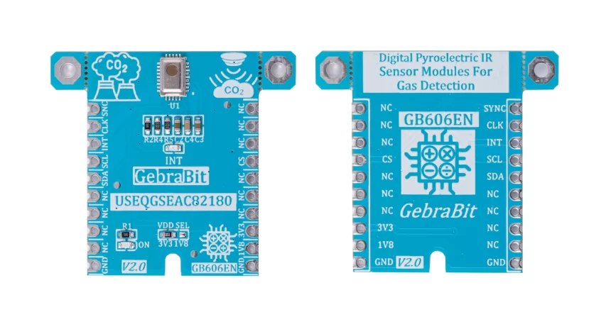
GebraBit USEQGSEAC82180 module

GebraBit USEQGSEAC82180 is a photoacoustic NDIR CO2 MEASUREMENT MODULE. GebraBit USEQGSEAC82180 operates with 3V3 and 5V Supply Voltages that users can easily select with jumper selector of the module. User can interface with GebraBit USEQGSEAC82180 by I2C protocol with the module. Also, Users can access to the interrupt (int) Pin of USEQGSEAC82180 through the GebraBit USEQGSEAC82180 module.
Since it’s difficult to access to sensor pins, the user needs a starter circuit and driver for the hardware development and of course the software development of the USEQGSEAC82180 sensor. For the convenience of users, this work has been done by implementing the USEQGSEAC82180 sensor circuit and providing access to the sensor important pins.

It is enough to put the GebraBit USEQGSEAC82180 module in the BreadBoard, then by applying the proper voltage set up the GebraBit USEQGSEAC82180 module with any of Arduino, Raspberry Pi, Discovery board, and especially we recommend using GebraBit microcontroller development modules (GebraBit STM32F303 or GebraBit ATMEGA32 module) then receiving the data.

The reason for our recommendation when setting up the GebraBit USEQGSEAC82180 module with GebraBit microcontroller development modules (such as GebraBit STM32F303 or GebraBit ATMEGA32), is the presence of an internal 3V3 regulator on these modules and the compatibility of the pin order of all GebraBit modules together (GEBRABUS standard), it’s enough to Put the USEQGSEAC82180 in the corresponding socket as shown in the above picture and develop the desired sensor module without the need for wiring.
Introduction of module sections

USEQGSEAC82180 sensor
USEQGSEAC82180 is the main IC of the following module which is located in the center of the module and its circuit is designed.

VDD SEL jumper
According to the state of 0R resistance of this jumper, the main voltage of sensor power supply is selected between 1V8 and 3V3.

Interrupt LED
A dedicated LED is considered for the interrupt pin on the module and its status changes when the interrupt state changes according to the sensor data sheet.

Power LED
According to the state of the VDD SEL jumper and applying voltage to the module by the corresponding pin, the LED of the module will be lit.

GebraBit USEQGSEAC82180 Module pins

Supply pins
- 3V3 and 1V8: These pins can supply the sensor main power supply and the logic level of the sensor digital connection (I2C) according to the state of the VDDSEL selector jumper.
- GND: This is the common ground pin for power and logic level of the sensor.

I2C pins
- SDA: This pin is the I2C communication data pin, which is connected to the corresponding data pin in the microcontroller (processor). According to the state of the VDD SEL jumper, you can use the logic level with a voltage of 1V8 or 3V3.This pin is pulled up with a resistor.
- SCL: This pin is the I2C communication clock pin, which is connected to the corresponding clock pin in the microcontroller (processor). Depending on the state of the VDD SEL jumper, you can use the logic level with a voltage of 1V8 or 3V3. This pin is pulled up with a resistor.

Other pins
- CK: This pin is the sensor clock pin. This pin is used for multiple USEQ package synchronisation and by default it’s an output pin.
- CS: This pin is the Chip Select pin for communication with the module (sensor) and can be controlled by MCU or connected to Vsupply.
- SYC: This pin is used for multiple USEQ package synchronisation. it’s an active low pin and by default it’s an output pin.
- INT: This pin is the interrupt output pin of the sensor and is an active low pin. Users should set it whenever there is data in the FIFO buffer (Normal Operation Mode) or an infrared event occurs (Sleep Mode).

Connect to the processor

I2C connection with GebraBit STM32F303
For I2C connection of GebraBit USEQGSEAC82180 and GebraBit STM32F303 microcontroller module, after defining SDA and SCL on pins PB9 and PB8 (for convenience in STMCUBEMX), follow the below steps:
- Connect the 3V3 pin of the USEQGSEAC82180 module to the 3V3 output pin of the microcontroller module. (Red wire)
- Connect the GND pin of the USEQGSEAC82180 module to the GND pin of the microcontroller module (Black wire).
- Connect the SCL pin of the USEQGSEAC82180 module to the PB8 pin of the microcontroller (SCL) module (Blue wire).
- Connect the SDA pin of the USEQGSEAC82180 module to the PB9 pin of the microcontroller (SDA) module. (Yellow wire)
You can see how to connect the above mentioned steps in this picture:

Note: Considering that the PA14 pin of the GebraBit STM32F303 microcontroller module is used to program the microcontroller, I2C setting on the PA14 and PA15 pins is impossible in this version, so in this version for I2C connection with the GebraBit STM32F303 microcontroller module, GebraBit USEQGSEAC82180 module cannot be placed on it as Pin to Pin. To make a more convenient connection between the two modules, you can select the SPI protocol by using the on-board jumpers and then place the GebraBit USEQGSEAC82180 module as Pin to Pin on the GebraBit STM32F303 module.
I2C connection with GebraBit ATMEGA32A
Considering that the I2C pins of the ATMEGA32A microcontroller are based on the GEBRABUS standard and correspond to the I2C pins of other GEBRABIT modules, the GebraBit USEQGSEAC82180 module can be placed pin to pin on the GebraBit ATMEGA32A module and communicate with the GebraBit USEQGSEAC82180 module via I2C. Here, for better understanding, the separate connection of these two modules is shown:

Note: If you are using GebraBit microcontroller modules, note that the jumper selectors of the GebraBit USEQGSEAC82180 are set to 3V3 so that you can easily power-on the GebraBit USEQGSEAC82180 module by getting the 3V3 voltage from the microcontroller module.
I2C Connection with ARDUINO UNO
Follow the below steps to connect the GebraBit USEQGSEAC82180 module to the ARDUINO UNO via I2C:
- Connect the 3V3 pin of the USEQGSEAC82180 module to the 3V3 output pin of the ARDUINO UNO board. (Red wire)
- Connect the GND pin of the USEQGSEAC82180 module to the GND pin of the ARDUINO UNO board (Black wire).
- Connect the SCL pin of the USEQGSEAC82180 module to the A5 pin of the ARDUINO UNO board (SCL). (Blue wire)
- Connect the SDA pin of the USEQGSEAC82180 module to the A4 pin of the ARDUINO UNO board (SDA). (Orange wire)
You can see how to connect the above mentioned steps in this picture:


