GebraBit

GebraBit MAX9812 Microphone Amplifier Module

متن سربرگ خود را وارد کنید

GebraBit MAX9812

GebraBit MAX9812 Microphone Amplifier Module

GebraBit MAX9812
  1. Home
  2. »
  3. Blog
  4. »
  5. GebraBit MAX9812 Microphone Amplifier Module

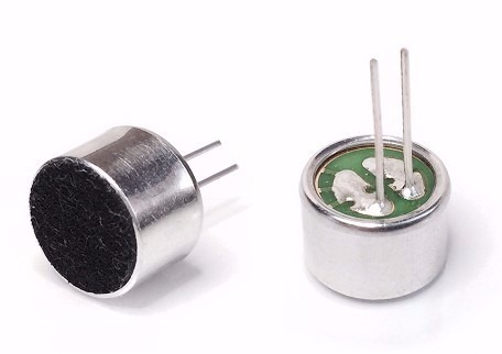
The microphone is a transducer device which converts sound energy into electrical energy. Microphones are often referred to a MIC. A microphone is used to capture some sort of sound and produce an electrical signal according to it.

A microphone has a sensitive component which converts the air pressure variations created by the sound wave into electrical signal. Depending on this component and the method to convert the sound wave into Electrical signal, there are various type microphones are available in the electronics and sound engineering field. Most common types are Dynamic Microphones, Condenser Microphone, Piezo electrical microphone etc.

The microphone generates the input for the sound sensor module and consists of a thin diaphragm that is one plate of a capacitor. The second plate of the capacitor is the back plate and in parallel to the diaphragm in very close distance. The following picture shows a basic schematic of the microphone.

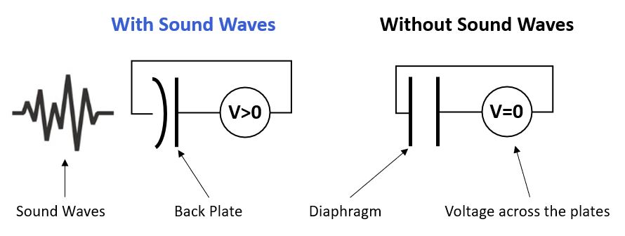
If someone speaks into the microphone, the sound waves created by the voice hit the diaphragm. Due to those hits, the diaphragm vibrates and therefore the distance between the two plates of the capacitor gets shorter or wider (picture on the left side).

Because the capacitance is directly proportional to the distance between the plates, the sound waves of the voice changes the voltage across the plates that has a direct influence of the circuit of the sensor module.

A mic preamp is a type of amplifier with the purpose of bringing mic level signals up to line level for use with professional equipment. Microphones output mic level signals and need preamps if they are to be used with mixing consoles, recording devices or digital audio workstations.

A microphone preamplifier is designed to take a microphone signal at its input; apply an appropriate amount of gain (typically adjustable), and output a line-level signal.

 A good microphone preamplifier should be able to apply at least 60 dB of gain to bring low-level mic signals (typically from dynamic or ribbon mics) up to line level.

An overview of the MAX9812 microphone amplifier

The MAX9812 is a single input, 20dB fixed-gain microphone amplifier  in a 6-pin SC70  package.

They offer tiny packaging and a low-noise, integrated microphone bias, making them ideal for portable audio applications such as notebook computers, cell phones, and PDAs.

This amplifier features a 500kHz bandwidth, rail-to-rail output and produced in two MAX9812L and MAX9812H  versions.

Specification

Applications

  • Output Type: Analog-Voltage (Rail-to-Rail)
  • GAIN: Fixed-20 dB
  • Frequency Range: 20 HZ to 20 KHZ
  • Sensitivity : – 44 dB ± 2 dB

For more specifications, please refer to datasheet

  • Single-Lead Event Monitors for Arrhythmia Detection
  • Single-Lead Wireless Patches for At-Home/ In-Hospital Monitoring
  • Chest Band Heart Rate Monitors for Fitness Applications
  • Bio Authentication and ECG-On-Demand Applications

GebraBit MAX9812 module Key Features

  • Highly-Sensitive Capacitive Microphone
  • On Board, ON/OFF LED indicator
  • Access to SHN pin of MAX9812 amplifier
  • GebraBit Pin Compatible with GEBRABUS
  • It can be used as a daughter board of GebraBit MCU Modules
  • Featuring Castellated pad (Assembled as SMD Part)
  • Separatable screw parts to reduce the size of the board
  • Package: GebraBit small (36.29mm x 32.72mm)

GebraBit MAX9812 module

GebraBit MAX9812

GebraBit MAX9812 features a microphone and Fixed-Gain Microphone Amplifier with Integrated Bias which operates just with a “5V” supply voltage.

Due to the SC70 package and lack of access to MAX9812 pins, users need a starter circuit and driver for the hardware development and of course the software development of the MAX9812 preamp. For the convenience of users, GebraBit provided it by implementing the MAX9812 preamp circuit and providing access to the important MAX9812 pins.

GebraBit MAX9812

To start this module, just put the GebraBit MAX9812 module in the BreadBoard, then you can start the module with any of Arduino, Raspberry Pi, Discovery board and by applying the proper voltage and you can read the output voltage through the internal ADC of each of these development modules. we recommend using GebraBit microcontroller development modules.  

The reason for our recommendation when setting up the GebraBit MAX9812 module with GebraBit microcontroller development modules (such as GebraBit STM32F303 or GebraBit ATMEGA32), is the compatibility of the pin order of all GebraBit modules together (GEBRABUS standard), it’s enough to Put the MAX9812 module in the corresponding socket as shown in the above picture and use the MAX9812 module easily. 

Introduction of module sections

microphone

The microphone used in this module is a condenser microphone and has two bases, one of them is connected to the input of the pre-amplifier and gives the audio signal output to the MAX9812 pre-amplifier as an input for applying the appropriate gain. Its other base is also connected to MAX9812 dedicated bias base to receive low-noise microphone bias input.

MAX9812 amplifier

It’s the main IC of the GebraBit MAX9812 module and improves the power of the received sound by receiving the output of the microphone and applying the appropriate gain.

power LED

By applying voltage to the module through the Power pins, this LED will be lit.

GebraBit MAX9812 Module pins

Supply pins

  • 5V: As mentioned earlier, the GebraBit MAX9812 module only works with 5V voltage. “5V” Pin has the task of providing this voltage.
  • GND: This is the ground pin of the module .

out pin

  • AO: MAX9812 Rail-to-Rail output is available on the “AO” pin. You can read the sound data, just by connecting the analog “AO” pin to MCU “ADC” pin.

shout-down pin

  • SHN: this pin is the Active-Low Shutdown Input pin. for normal operation you should Connect the “SHDN” to “VCC” and for shutdown ,Connect the “SHDN” to “GND”. “SHDN” is a high-impedance input; do not leave this pin unconnected.

Connect to the processor

connection to GebraBit STM32F303

To Set-up the GebraBit MAX9812 with the GebraBit STM32F303 you can simply place the GebraBit MAX9812 module pin to pin on the GebraBit STM32F303 module and start the module by applying “5V” voltage:

connection to GebraBit ATMEGA32A

To Set-up the GebraBit MAX9812 with the GebraBit ATMEGA32A you can simply place the GebraBit MAX9812 module pin to pin on the GebraBit ATMEGA32A module and start the module by applying “5V” voltage:

connect to ARDUINO UNO

Follow the steps below to connect GebraBit MAX9812 module to ARDUINO UNO:

  • Connect the “5V” pin of the MAX9812 module to the “5V” output pin of the ARDUINO UNO board. (red wire)
  • Connect the “GND” pin of the MAX9812 module to the “GND” pin of the ARDUINO UNO board (black wire).
  • Connect the analog pin “AO” of the MAX9812 module to one of the analog pins of the ARDUINO UNO board(e.g.”A0”). (blue wire)
  • Connect the “SHN” pin of the MAX9812 module to one of the digital pins of the ARDUINO UNO board (e.g.”D6”)(green wire).

You can see how to connect the above mentioned steps, in the below picture:

این مقاله را با دوستانتان به اشتراک بگذارید!

Leave a Reply

Your email address will not be published. Required fields are marked *

Shopping cart
Start typing to see posts you are looking for.

Sign in

No account yet?