GebraBit

GebraBit IIM42352 Accelerometer Module Overview

متن سربرگ خود را وارد کنید

BLOG

GebraBit IIM42352 Accelerometer Module Overview

  1. Home
  2. »
  3. Blog
  4. »
  5. GebraBit IIM42352 Accelerometer Module Overview

Up until the emergence of microelectromechanical systems (MEMS) technology, inertial sensors were high-cost, precision instruments, typically reserved for high-end applications. As MEMS technology has matured, low-cost solid-state chip level inertial sensors have become available as alternatives to the larger high-end inertial sensors. This addition of MEMS to the inertial sensing market has provided a wide variety of performance capabilities and allowed inertial sensing technology to be used in more applications than ever before.


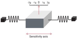
An accelerometer is the primary sensor responsible for measuring inertial acceleration, or the change in velocity over time, and can be found in a variety of different types, including mechanical accelerometers, quartz accelerometers, and MEMS accelerometers. A MEMS accelerometer is essentially a mass suspended by a spring, as illustrated in Figure below. The mass is known as the proof mass and the direction that the mass is allowed to move is known as the sensitivity axis.

When an accelerometer is subjected to a linear acceleration along the sensitivity axis, the acceleration causes the proof mass to shift to one side, with the amount of deflection proportional to the acceleration.

An overview of the IIM42352 Accelerometer

IIM42352 accelerometer

The IIM42352 is a 3-axis accelerometer in a small 2.5 mm x 3 mm x 0.91 mm (14-pin LGA) package. It also features a 2K-byte FIFO that can lower the traffic on the serial bus interface and reduce power consumption by allowing the system processor to burst read sensor data and then go into a low-power mode. IIM42352, with its 3-axis integration, enables manufacturers to eliminate the costly and complex selection, qualification, and system level integration of discrete devices, guaranteeing optimal motion performance for consumers.
The accelerometer supports four programmable full-scale range settings from ±2g to ±16g.

Other industry-leading features include on-chip 16-bit ADCs, programmable digital filters, an embedded temperature sensor, and programmable interrupts. The device features I3C, I2C, and SPI serial interfaces

Specification

Applications

  • Number of Axis: 3-Axis
  • Output type: Digital – I2C or I3C or SPI
  • Accelerometer  FSR: ±2, ±4, ±8, ±16(g)
  • Accelerometer Sensitivity SF: 16384, 2048 (LSB/g), 4096, 8192
  •  Accelerometer ADC: 16 Bit

For more specifications, please refer to the Datasheet

  • Vibration measurement
  • Predictive maintenance
  • Tilt sensing
  • Platform stabilization
  • Robotics

GebraBit IIM42352 Module Key Features

  • User-selectable module power supply voltage between 1V8 and 3V3
  • User-selectable module I/O logic voltage between 1V8 and 3V3
  • User-selectable interface protocol (I2C or SPI)
  • User-selectable I2C address (AD0)
  • Access to all data pins of the sensor
  • On Board, ON/OFF LED indicator
  • Pin Compatible with GEBRABUS
  • It can be used as a daughter board of GebraBit MCU Modules
  • Featuring Castellated pad (Assembled as SMD Part)
  • Separatable screw parts to reduce the size of the board
  • Package: GebraBit small (36.29mm x 32.72mm)
  • Schematic (.pdf)

GebraBit IIM42352 module

GEBRABIT IIM42352

After the explanations mentioned above , due to LGA package and lack of access to sensor pins, you have noticed that, the user needs a starter circuit and driver for the hardware development and of course the software development of the IIM42352 sensor. For the convenience of users, this work has been done by implementing the IIM42352 sensor circuit and providing access to the communication and power supply signal pins, with the ability to select the I2C or SPI communication protocol and the operation voltage and logic level of the communication protocols.

GEBRABIT IIM42352

It is enough to put the GebraBit IIM42352 module in the BreadBoard, then you can set up the GebraBit IIM42352 module by applying the proper voltage and choosing the I2C or SPI communication protocol, with any of Arduino, Raspberry Pi, Discovery board, and especially we recommend using GebraBit microcontroller development modules( GebraBit STM32F303 or GebraBit ATMEGA32 module) then receiving the data.

The reason for our recommendation when setting up the GebraBit IIM42352 module with GebraBit microcontroller development modules (such as GebraBit STM32F303 or GebraBit ATMEGA32), is the presence of an internal 3V3 regulator on these modules and the compatibility of the pin order of all GebraBit modules together (GEBRABUS standard), it’s enough to Put the IIM42352 in the corresponding socket as shown in the above picture and develop the desired sensor module without the need for wiring.  

Introduction of module sections

IIM42352 sensor

It’s the main IC of the following module, which is placed in the center of the module and its circuit is designed.

Communication Protocol Selection Jumpers

If the 0R resistors of all Selector Jumpers are to the left side, the I2C protocol is selected. 

If the 0R resistors of all Selector Jumpers are to the right side, the SPI protocol is selected. 

by default,I2C protocol is selected. 

AD0 SEL jumper

If the I2C protocol is selected, the state of AD0 SEL jumper, determines the I2C address of the sensor (0 => 0x68 or  1 =>0x69).

The 0R resistor is set to 0 and the address 0x68 is selected (by default).

VDIO SEL jumper

According to the state of 0R resistance of this jumper, the logic level of digital communication (I2C or SPI) of the sensor is selected between “1V8” and “3V3”.

The digital communication logic level (I2C or SPI) of the sensor is selected “3V3” (by default).

VDD SEL jumper

According to the state of 0R resistance of this jumper, the main voltage of the sensor power supply  is selected between “1V8” and “3V3”.

The main sensor power supply voltage is “3V3” (by default).

power LED

According to the state of the “VDD SEL” jumper and applying voltage to the module by the corresponding pin, the LED of the module will be lit.

GebraBit IIM42352 Module pins

Supply pins

  • 3V3: This pin can supply the sensor main power supply and the logic level of the sensor digital connection (I2C or SPI) according to the state of the “VDD SEL” and “VDIO SEL” selector jumpers.
  • 1V8: This pin can supply the sensor main power supply and the logic level of the sensor digital communication (I2C or SPI) according to the state of the “VDD SEL” and “VDIO SEL” selector jumpers.
  • GND: This is the common ground pin for power and logic level of the sensor.

I2C pins

By using the on-board embedded Jumper selectors, you can choose the type of module communication  . If the 0R resistors of all the Selector Jumpers are to the left side, the ” I2C ” protocol is selected. “AD0 SEL”  jumper status is the I2C address of the sensor (0x68 or 0x69 ).

    • SDA: This pin is the I2C communication data pin, which is connected to the corresponding data pin in the microcontroller (processor). According to the state of the “VDIO SEL” jumper, you can use the logic level with a voltage of “1V8” or “3V3”.This pin is pulled up with a 10K resistor.
    • SCL: This pin is the I2C communication clock pin, which is connected to the corresponding clock pin in the microcontroller (processor). Depending on the state of the “VDIO SEL” jumper, you can use the logic level with a voltage of “1V8” or “3V3”. This pin is pulled up with a 10K resistor.

SPI pins

The type of communication with the module can be selected by using the on-board embedded Selector Jumpers. If the 0R resistors of all the Selector Jumpers are to the right side, the SPI protocol has been selected. The state of the “AD0 SEL” jumper has no effect in this case.

  • SDI (MOSI): This pin is used to send data from the microcontroller (processor) to the module (sensor). The abbreviation of this pin is derived from the Latin phrase Serial Data In / Microcontroller Out Sensor In.
  • SDO (MISO): This pin is used to send data from the module (sensor) to the microcontroller (processor). The abbreviation of this pin is derived from the Latin phrase Serial Data Out / Microcontroller In Sensor Out.
  • SCK: This pin is the clock pin for SPI communication, which is considered as an input for the sensor and is connected to the corresponding clock pin in the microcontroller (processor).
  • CS: This pin is the Chip Select pin for SPI communication with the module (sensor), which is selected by applying LOW voltage (0V), the module (sensor) for SPI communication. This pin is input type for the sensor.

If you want to use several GebraBit IIM42352 modules at the same time, it is enough to connect the “SDO”, “SDI”, “SCK” pins of all modules and the microcontroller (processor) and assign a unique pin to each “CS”.

Other pins

  • INT: Interrupt pin for IIM42352 sensor, according to the datasheet , the user can set the interrupt conditions, the modes and methods of the interruption, etc.
  • FSY(FSYNC): This pin is used to synchronize the sensor with an external source. For more information, read the datasheet of the sensor. By default, this pin is connected to the ground with R3 resistor. To use Pin, R3 resistor must be removed (disassembly) from the module.

Connect to the processor

I2C connection with GebraBit STM32F303

First, make sure that the I2C protocol is selected by using the on-board jumpers, then for i2c communication of GebraBit IIM42352 and GebraBit STM32F303 microcontroller module, after defining “SDA” and “SCL” on pins PB9 and PB8 (for convenience in STMCUBEMX), follow the below steps:

  • Connect the “3V3” pin of the IIM42352 module to the “3V3” output pin of the microcontroller module. (red wire)
  • Connect the “GND” pin of the IIM42352 module to the “GND” pin of the microcontroller module (black wire).
  • Connect the “SCL” pin of the IIM42352 module to the PB8 pin of the microcontroller (SCL) module (blue wire).
  • Connect the “SDA” pin of the IIM42352 module to the PB9 pin of the microcontroller (SDA) module. (yellow wire)

You can see how to connect the above mentioned steps, in the below picture:

Note: Considering that the PA14 pin of the GebraBit STM32F303 microcontroller module is used to program the microcontroller, I2C setting on the PA14 and PA15 pins is impossible in this version, so in this version for  I2C  connection with the GebraBit STM32F303 microcontroller module, GebraBit IIM42352 module cannot be placed on it as Pin to Pin. To make a more convenient connection between the two modules, you can select the SPI protocol by using the on-board jumpers and then place the GebraBit IIM42352 module as Pin to Pin on the GebraBit STM32F303 module.    

SPI connection with GebraBit STM32F303

First, make sure that the SPI protocol is selected by using the on-board jumpers, then for connecting GebraBit IIM42352 module to the GebraBit STM32F303 microcontroller module with SPI protocol, after defining “SDI”, “SDO”, “SCK”, and “CS” on pins PB5, PB4, PB3, and PC13 ( For ease of work in STMCUBEMX) place the GebraBit IIM42352 module Pin to Pin on the GebraBit STM32F303 module easily. Here the separate connection of the modules is shown for better understanding.

SPI or I2C connection with GebraBit ATMEGA32A

Considering that the SPI and I2C pins of the ATMEGA32A microcontroller are based on the GEBRABUS standard and correspond to the SPI and I2C pins of other GEBRABIT modules, the GebraBit IIM42352 module can be placed pin to pin  on the GebraBit ATMEGA32A module and communicate with the GebraBit IIM42352 module via SPI or I2C by changing the state of the protocol selection jumper resistors. Here the separate connection of the modules is shown for better understanding.

I2C Connection
SPI Connection

NOTE: If you are using GebraBit microcontroller modules, note that the power selector jumpers of the GebraBit IIM42352 are set to “3V3” so that you can easily power-on the GebraBit IIM42352 module by getting the “3V3” voltage from the microcontroller module.

I2C Connection with ARDUINO UNO

First, make sure that the I2C protocol is selected by using the on-board jumpers, then follow the below steps to connect the GebraBit IIM42352 module to the ARDUINO UNO via I2C :

  • Connect the “3V3” pin of the IIM42352 module to the “3V3” output pin of the ARDUINO UNO board. (red wire)

Connect the “GND” pin of the IIM42352 module to the “GND” pin of the ARDUINO UNO board (black wire).

  • Connect the “SCL” pin of the IIM42352 module to the A5 pin of the ARDUINO UNO board (SCL). (blue wire)
  • Connect the “SDA” pin of the IIM42352 module to the A4 pin of the ARDUINO UNO board (SDA). (orange wire)

You can see how to connect the above mentioned steps, in the below picture:

SPI Connection with ARDUINO UNO

First, make sure the SPI protocol is selected using the on-board jumpers, then follow the below  steps to connect the GebraBit IIM42352 module to the ARDUINO UNO via SPI:

  • Connect the “3V3” pin of the IIM42352 module to the “3V3” output pin of the ARDUINO UNO board. (red wire)
  • Connect the “GND” pin of the IIM42352 module to the “GND” pin of the ARDUINO UNO board (black wire).
  • Connect the “SDI” pin of the IIM42352 module to the D11 pin of the ARDUINO UNO board (SDI). (yellow wire)
  • Connect the “SDO” pin of the IIM42352 module to the D12 pin of the ARDUINO UNO board (SDO). (Purple wire)
  • Connect the “SCK” pin of the IIM42352 module to the D13 pin of the ARDUINO UNO board (SCK). (Orange wire)
  • Connect the “CS” pin of the IIM42352 module to the D10 pin of the ARDUINO UNO board (CS). (blue wire)

You can see how to connect the above mentioned steps, in the below picture:

این مقاله را با دوستانتان به اشتراک بگذارید!

Leave a Reply

Your email address will not be published. Required fields are marked *

Shopping cart
Start typing to see posts you are looking for.

Sign in

No account yet?