GebraBit

GebraBit HTU31D Relative Humidity and Temperature Sensor Module Overview

متن سربرگ خود را وارد کنید

HTU31 both sides

GebraBit HTU31D Relative Humidity and Temperature Sensor Module Overview

  1. Home
  2. »
  3. Blog
  4. »
  5. GebraBit HTU31D Relative Humidity and Temperature Sensor Module Overview

Temperature is the measure of warmth or coldness in reference to a set standard, often expressed in terms of degrees Fahrenheit or Celsius. Humidity refers to the amount of water vapor, or moisture, in the air.

There are generally two types of humidity ie. absolute and relative. The former tells the humidity present in a parcel of air without taking temperature into consideration whereas the latter tells the humidity present in the air concerning the temperature of the air.

If temperature increases it will lead to a decrease in relative humidity, thus the air will become drier whereas when temperature decreases, the air will become wet means the relative humidity will increase.

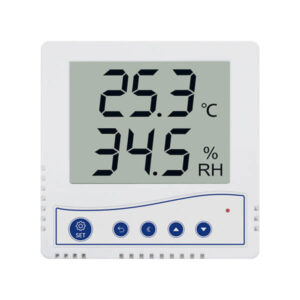
Temperature and humidity sensor are devices that can convert temperature and humidity into electrical signals that can easily measure temperature and humidity. Temperature humidity transmitters  available on the markets, generally measure the amount of temperature and relative humidity in the air, and convert it into electrical signals or other signal forms according to certain rules and output the signal to the instrument or software to meet the environmental monitoring needs of users.

An overview of the HTU31D sensor

The HTU31 is one of the smallest and most accurate humidity sensors on the market with fast response time, precision measurement, low hysteresis, robustness to reflow assembly process and sustained performance even when exposed to extreme temperature and humidity environments.The HTU31 humidity & temperature sensor includes both digital (D) and analog (V) versions.

Specification

Applications

  • Output type: Digital-I2C
  • Humidity rangege: 0 to 100 %RH
  • Temperature range: -40°C to +125°C

For more specifications, please refer to datasheet

  • Humidifiers / Dehumidifier
  • Meteorology
  • Environmental Monitoring & Trackers
  • IoT Applications/ IP Camera
  • Water Leak Detector

HTU31D module Key Features

  • User-selectable module power supply voltage between 3V3 and 5V
  • Selectable I2C address
  • Access to Reset pin of SHT35
  • ON/OFF LED indicator
  • GebraBit Pin Compatible with GEBRABUS
  • It can be used as a daughter board of GebraBit MCU Modules
  • Featuring Castellated pad (Assembled as SMD Part)
  • Separatable screw parts to reduce the size of the board
  • Package: GebraBit small (36.29mm x 32.72mm)

GebraBit HTU31D module

GebraBit HTU31D is a digital humidity and temperature measurement module.

GebraBit HTU31D operates with 3V3 and 5V Supply Voltages that users can easily select with jumper selector of the module.

User can interface with GebraBit HTU31D by I2C protocol and capable of setting I2C address with jumper selector of the module.

another important feauture of GebraBit HTU31D is that user access to reset pin of the HTU31D through RST pin of module for reset the module.

Considering that it is difficult to access the sensor pins, the user needs a starter circuit and driver for the hardware development and of course the software development of the HTU31D sensor. GebraBit implements the HTU31D sensor circuit and provides access for the convenience of users.

It is enough to put the GebraBit HTU31D module in the BreadBoard, then by applying the proper voltage set up the GebraBit HTU31D module with any of Arduino, Raspberry Pi, Discovery board, and especially we recommend using GebraBit microcontroller development modules (GebraBit STM32F303 or GebraBit ATMEGA32 module) then receive the data.     

The reason for our recommendation when setting up the GebraBit HTU31D module with GebraBit microcontroller development modules (such as GebraBit STM32F303 or GebraBit ATMEGA32), is the presence of an internal 3V3 regulator on these modules and the compatibility of the pin order of all GebraBit modules together (GEBRABUS standard), it’s enough to Put the HTU31D in the corresponding socket as shown in the above picture and develop the desired sensor module without the need for wiring.   

Introduction of module sections

HTU31D sensor

HTU31D sensor is the Relative Humidity and Temperature sensor of this module which its circuit is designed.

VCC SEL

According to the state of 0R resistance of this jumper, the main voltage of the sensor power supply is selected between “5V” and “3V3”.

ADD SEL

HTU31 series has the capability to respond 2 distinct I²C addresses. This feature allows to use multiple sensors on the same I²C network and avoid address conflict with other components. For this purpose, the ADD SEL selector jumper is installed on the GebraBit HTU31D module so that the user can easily change the I2C address of the sensor by changing the ADD SEL 0R resistance then users are able to use multiple sensors on the same I2C network.

The sensor I2C address table is as follows:

Power supply LED

According to the state of the VCC SEL jumper and applying voltage to the module by the corresponding pin, the LED of the module will be lit.

GebraBit HTU31D Module pins

Supply pins

  • 3V3 and 5V: These pins can supply the sensor main power supply and the logic level of the sensor digital connection (I2C) according to the state of the VCC SEL selector jumper.
  • GND: This is the common ground pin for power and logic level of the sensor.

I2C pins

  • SDA: This pin is the I2C communication data pin, which is connected to the corresponding data pin in the microcontroller (processor). According to the state of the VCCSEL jumper, you can use the logic level with a voltage of 5V or 3V3.
  • SCL: This pin is the I2C communication clock pin, which is connected to the corresponding clock pin in the microcontroller (processor). Depending on the state of the VCCSEL jumper, you can use the logic level with a voltage of 5V or 3V3.

Reset pin

The RST pin can be used to generate a reset of the sensor. A minimum pulse of 1 μs is required to reliably trigger a sensor reset.

Connect to the processor

I2C connection with GebraBit STM32F303

for i2c communication of GebraBit HTU31D and GebraBit STM32F303 microcontroller module, after defining SDA and SCL on pins PB9 and PB8 (for convenience in STMCUBEMX), follow the below steps:

  • Connect the 3V3 pin of the HTU31D module to the 3V3 output pin of the microcontroller module. (red wire)
  • Connect the GND pin of the HTU31D module to the GND pin of the microcontroller module (black wire).
  • Connect the SCL pin of the HTU31D module to the PB8 pin of the microcontroller (SCL) module (blue wire).
  • Connect the SDA pin of the HTU31D module to the PB9 pin of the microcontroller (SDA) module. (yellow wire)

Note: Considering that the PA14 pin of the GebraBit STM32F303 microcontroller module is used to program the microcontroller, I2C setting on the PA14 and PA15 pins is impossible in this version, so in this version for  I2C  connection with the GebraBit STM32F303 microcontroller module, GebraBit HTU31D module cannot be placed as Pin to Pin on it.

I2C connection with GebraBit ATMEGA32A

Considering that the I2C pins of the ATMEGA32A microcontroller are based on the GEBRABUS standard and correspond to the I2C pins of other GEBRABIT modules, the GebraBit HTU31D  module can be placed pin to pin  on the GebraBit ATMEGA32A module Here, for better understanding, the separate connection of these two modules is shown.

NOTE: If you are using GebraBit microcontroller modules, note that the power selector jumper of the GebraBit HTU31D is set to 3V3 so that you can easily power-on the GebraBit HTU31D  module by getting the 3V3 voltage from the microcontroller module.

I2C Connection with ARDUINO UNO

follow the below steps to connect the GebraBit HTU31D module to the ARDUINO UNO:

  • Since the VCC SEL jumper is set to 3V3, connect the “3V3” pin of the HTU31D module to the “3V3” output pin of the ARDUINO UNO board. (Red wire)
  • Connect the SCL pin of the HTU31D module to the A5 pin of the ARDUINO UNO board (SCL). (blue wire)
  • Connect the SDA pin of the HTU31D module to the A4 pin of the ARDUINO UNO board (SDA). (orange wire)

How to connect the above mentioned steps, can be seen in this picture:

این مقاله را با دوستانتان به اشتراک بگذارید!

Leave a Reply

Your email address will not be published. Required fields are marked *

Shopping cart
Start typing to see posts you are looking for.

Sign in

No account yet?