WIFI is a type of technology that enables devices including computers mobile devices and other equipment to interface with the internet. The connection is made via a wireless router.
Wi-Fi modules (wireless fidelity) also known as WLAN modules (wireless local area network) are Wireless modules are used in a variety of industrial, scientific, consumer and commercial applications. With Wi-Fi modules, utilities and service providers, as well as their customers, can communicate directly with water heaters, air conditioning systems, thermostats and other electrical products in the home. Electronic components used in many products to achieve a wireless connection to the internet.
An overview of the ESP8266

ESP8266EX delivers highly integrated Wi-Fi SoC solution to meet users’ continuous demands for efficient power usage, compact design and reliable performance in the Internet of Things industry. With the complete and self-contained Wi-Fi networking capabilities, ESP8266EX can perform either as a standalone application or as the slave to a host MCU. The integrated high- speed cache helps to increase the system performance and optimize the system memory. Also, ESP8266EX can be applied to any microcontroller design as a Wi-Fi adaptor through SPI/SDIO or UART interfaces.
Specification
Application
- Output type: Digital-UART
- Wi-Fi Protocol:802.11 b/g/n (HT20)
- Frequency Range: 2.4 GHz ~ 2.5 GHz (2400 MHz ~ 2483.5 MHz)
- CPU: Tensilica L106 32-bit processor
- User Configuration: Android/iOS App, AT Instruction Set, Cloud Server
- ADC Resolution: 10Bit
For more specifications, please refer to datasheet
- Home automation
- Smart plugs and lights
- Industrial wireless control
- Baby monitors
- IP cameras
- Sensor networks
- Wearable electronics
- Wi-Fi location-aware devices
- Security ID tags
- Wi-Fi position system beacons
ESP8266 module Key Features
- PCB trace antenna
- 8M-bit Serial Flash memory
- Access to important pins of ESP8266EX
- Just 5V input voltage is sufficient for powering the module on
- 3V3 Voltage Regulator
- 3V3 Output Voltage
- ON/OFF LED indicator
- Capability of programming and firmware upgrading by UART and GPIO0 pins.
- 26 Mhz SMD CRYSTAL
- Pin Compatible with GEBRABUS
- GebraBit small package
- It can be used as a daughter board of GEBRABIT MCU Modules
- Featuring Castellated pad (Assembled as SMD Part)
- Separatable screw parts to reduce the size of the board
GebraBit ESP8266 module

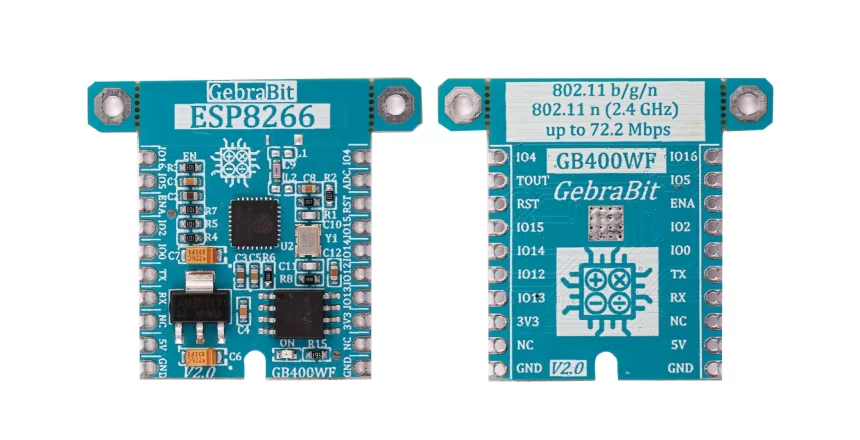
GebraBit ESP8266 is an integrated Wi-Fi SoC Module that meets users’
Continuous demands for efficient power usage, compact design, and reliable performance in the Internet of Things industry.
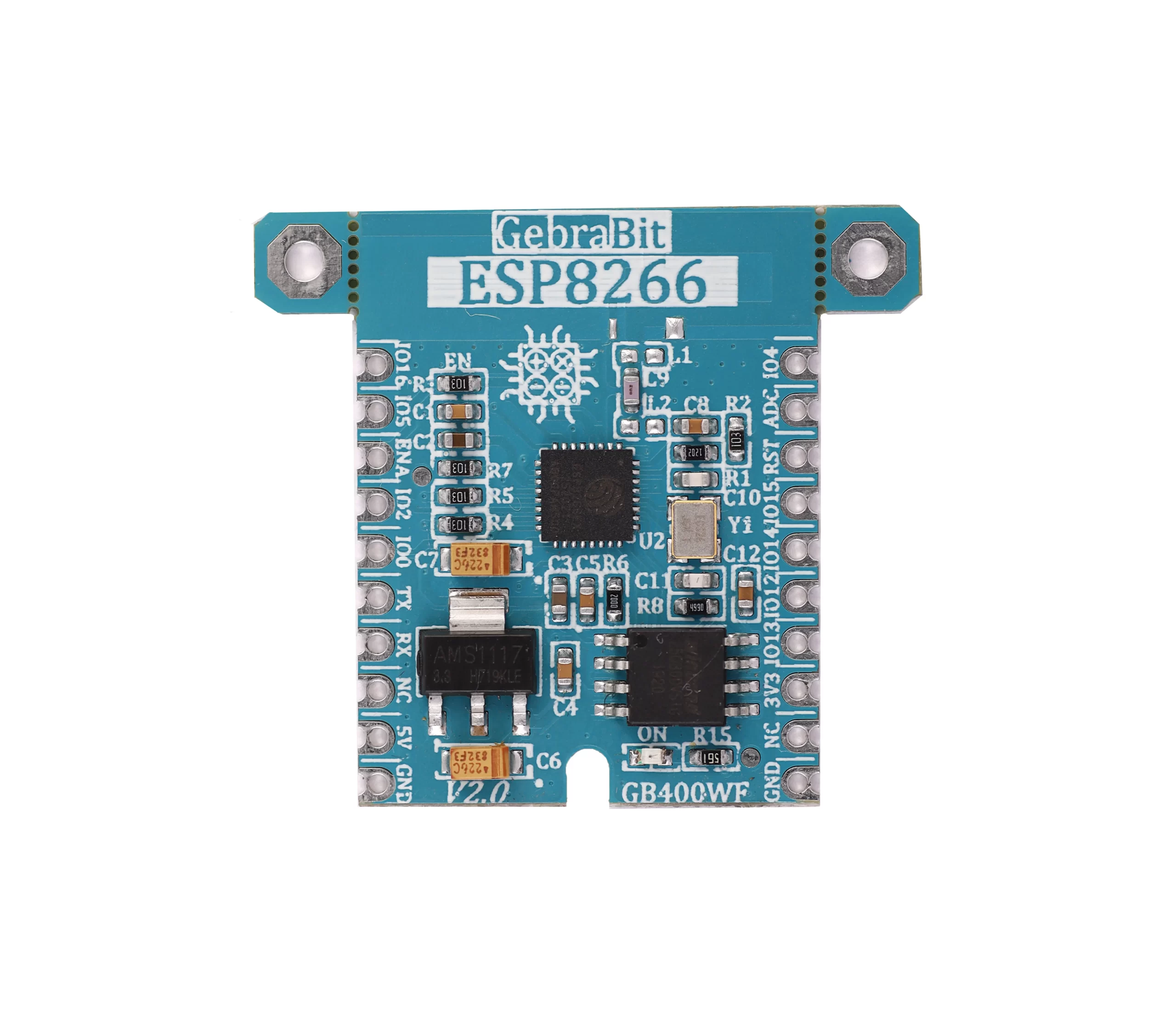
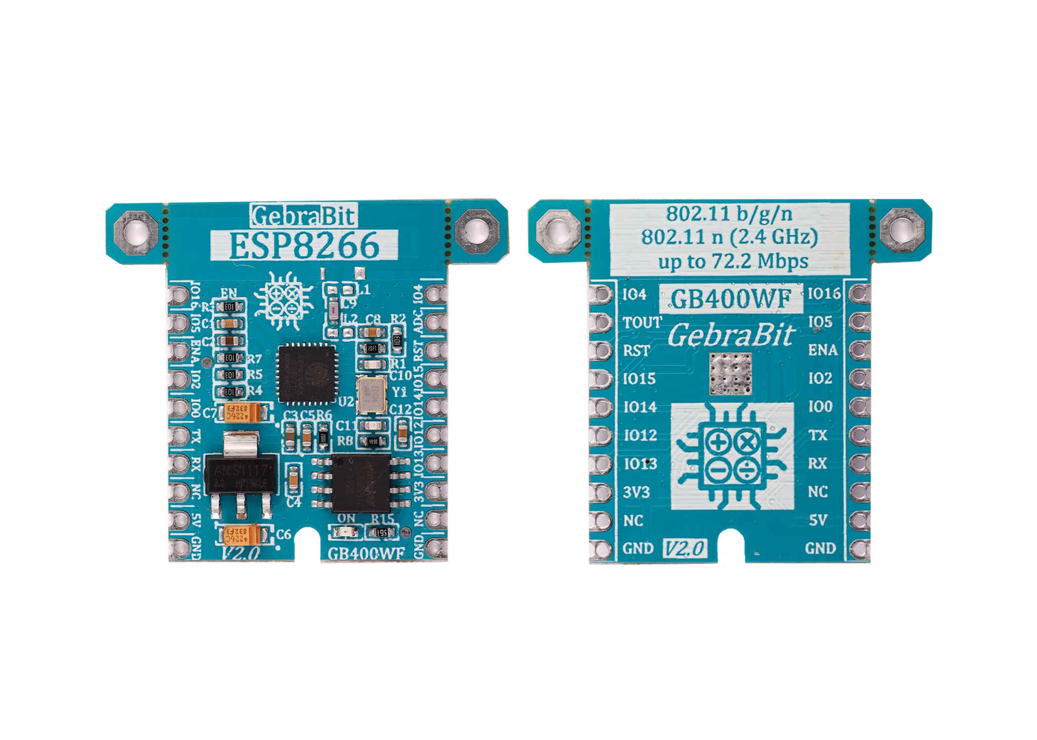
GebraBit ESP8266, which features a PCB antenna and 26Mhz crystals, operates with a 5V input Supply Voltage due to an integrated 3V3 regulator which its output is accessible on the “3V3” pin. Also, Users can access the most important pins of the ESP8266 through the GebraBit ESP8266 module. Pins like HSPI, UART, I2C, I2S, IR REMOTE CONTROL, PWM, ADC, ENABLE, RESET, and GPIO. Users can program and upgrade the ESP8266 firmware in (8M-bit) Serial Flash memory through UART and GPIO0 pins.
Although ESP8266 on this module is enabled by default through the ‘R3’ resistor, users can control ESP8266 by the ‘ENA’ pin. The GebraBit ESP8266 module can be driven via the serial interface using the standard AT commands.

To start this module, just put the GebraBit ESP8266 module in the BreadBoard, and then start the module by applying the proper voltage. You can Set-up the GebraBit ESP8266 module with any of Arduino, Raspberry Pi, Discovery board, and receive the data. We especially recommend you to use GebraBit microcontroller modules ( GebraBit STM32F303 or GebraBit ATMEGA32 module) for developing GebraBit ESP8266.

The reason for our recommendation when setting up the GebraBit ESP8266 module with GebraBit microcontroller development modules (such as GebraBit STM32F303 or GebraBit ATMEGA32), is the presence of an internal 3V3 regulator on these modules and the compatibility of the pin order of all GebraBit modules together (GEBRABUS standard), it’s enough to Put the ESP8266 in the corresponding socket as shown in the above picture and develop the desired sensor module without the need for wiring.
Introduction of module sections

ESP8266 IC
ESP8266 is the main IC of this module, which is placed in the center of this module and its circuit is designed.

26MHz external oscillator crystal
In ESP8266, a high frequency clock is used to drive both transmit and receive mixers. This clock can be provided both through the internal crystal oscillator and through the external crystal oscillator, for this purpose, a 26MHz external crystal oscillator has been used in the GebraBit ESP8266 module.

AMS1117 regulator
A 3V3 regulator is used in the design of the GebraBit ESP8266 module. The output of this regulator is available through the 3V3 pin.

8M-Bit flash memory
ESP8266 uses an external flash memory to store user programs, for this purpose an 8M bit memory has been used in the design of this module.

Power LED
By applying voltage to the module through the corresponding pin, this LED will be lit.

GebraBit ESP8266 Module pins

Supply pins
- 5V: GebraBit ESP8266 module works with 5V voltage because of the 3V3 regulator, and for this reason, the 5V pin is responsible for supplying the module supply voltage.
- 3V3: The output of the 3V3 regulator is available through this pin.
- GND: This pin is the ground pin for powering the module.

GPIO pins
- I/O: The ESP8266 has 17 GPIO pins that can be assigned different functions by programming the appropriate registers. Although the ESP8266 has a lot of pins with various functions, some of them may not be suitable for your projects.
In the GebraBit ESP8266 module, the pins that are suitable for projects are available to the user.
You should only note that among these pins, IO16, IO15 and IO0 pins are used for IC boot and it is better to use them as GPIO pins only when necessary.
All the GPIO pins of this IC except the IO16 pin can be used as interrupt pins.

UART pins
The GebraBit ESP8266 module has a UART interface. RX and TX pins are used to communication and during flash memory programming.
- TXD: This pin is used for sending data from the module to other devices.
- RXD: This pin is used for receiving data from other devices to the module.
When using this interface, note that the TX pin of the ESP8266 module must be connected to the RX pin and its RX pin must be connected to the TX pin of the opposite microcontroller/device.

Other pins
- ENA: This pin is the enable pin of the ESP8266 IC. When it is in High mode, the IC is active and when it is in Low mode, the IC is disabled. This pin is High by default.
- RST: This pin is the ESP8266 reset pin, which by default is in High state, when it is momentarily Low, it resets ESP8266.
- ADC: This pin is the ESP8266 analog to digital converter pin.

Connect to the processor

Connect to GebraBit STM32F303
Due to the compatibility of the GebraBit STM32F303 microcontroller pins with the GebraBit ESP8266 module pins (according to the GEBRABUS standard), to connect the GebraBit ESP8266 module to the GebraBit STM32F303 module, you can easily place it as Pin to Pin on the GebraBit STM32F303 module and start the module.
Here, for better understanding, the separate connection of these two modules is shown.

Connect with GebraBit ATMEGA32A
Due to the compatibility of the GebraBit ATMEGA32A microcontroller pins with the GebraBit ESP8266 module pins (according to the GEBRABUS standard), to connect the GebraBit ESP8266 module to the GebraBit ATMEGA32A module, you can easily place it as Pin to Pin on the GebraBit ATMEGA32A module.
Here, for better understanding, the separate connection of these two modules is shown.

Connect to ARDUINO UNO
Follow the below steps to connect the GebraBit ESP8266 module to the ARDUINO UNO:
- Connect the “5V” pin of ESP8266 module to the “5V” output pin of the ARDUINO UNO board. (Red wire)
- Connect the “GND” pin of the ESP8266 module to the “GND” pin of the ARDUINO UNO board (black wire).
- Connect the “TX” pin of the ESP8266 module to TX pin of the ARDUINO UNO board. (Orange wire)
- Connect the “RX” pin of the ESP8266 module to RX pin of the ARDUINO UNO board. (Yellow wire)
You can see how to connect the above mentioned steps, in the below picture:


