Biomedical sensors are special electronic devices that can transduce biomedical signals into easily measurable electric signals. Biomedical sensors are the key component in various medical diagnostic instruments and equipment.
Biomedical sensors have been widely applied in medical image analysis and diagnostics, portable and clinical diagnostics, and laboratory analytical applications.
Biomedical sensors are usually classified according to the quantity to be measured and are typically categorized as physical, electrical, or chemical, depending on their specific applications.

An electrocardiogram records the electrical signals in the heart. It’s a common and painless test used to quickly detect heart problems and monitor the heart’s health. An electrocardiogram — also called ECG or EKG — is often done in a health care provider’s office, a clinic or a hospital room. ECG machines are standard equipment in operating rooms and ambulances. Some personal devices, such as smartwatches, offer ECG monitoring.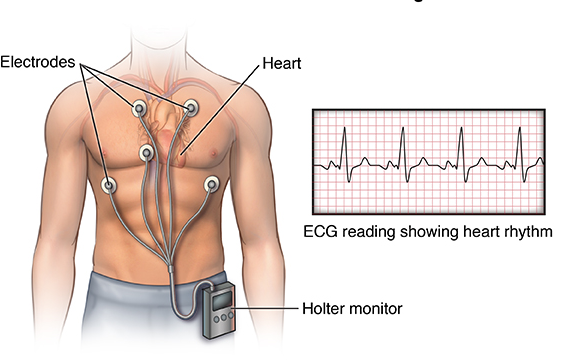
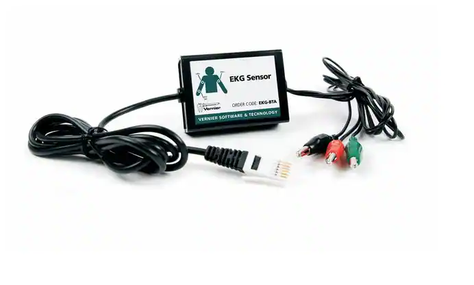
An overview of the AD8232 sensor

AD8232 is a single-lead front-end heart rate monitor sensor with Rail-to-Rail output which is packaged in a 4 mm × 4 mm, 20-lead LFCSP package and is operational from −40°C to +85°C .
It is designed to extract, amplify, and filter small biopotential signals in the presence of noisy condition. This design allows for an ultralow power analog-to-digital converter (ADC) or an embedded microcontroller to acquire the output signal easily.
The features of this sensor include Internal RFI filter, 3-pole adjustable low-pass filter with adjustable gain, Integrated right leg drive (RLD) amplifier, ac or dc Leads off detection options and 8 kV HBM ESD rating, and etc.
This sensor can be used in Fitness and activity heart rate monitors, Portable ECG, Remote health monitors, Gaming peripherals, Biopotential signal acquisition.
Specification
Applications
- Output type: Analog – Voltage
- Data rate: 360SPS to 2KSPS
For more specifications, please refer to datasheet
- Fitness and activity heart rate monitors
- Portable ECG
- Remote health monitors
- Gaming peripherals
- Biopotential signal acquisition
GebraBit AD8232 module Key Features
- 3V3 input voltage
- Can use 3-lead ECG cable with 3.5mm phone male jack
- LED indicator for heart rate
- ON/OFF LED indicator
- Access to important I/O of AD8232
- Pin Compatible with GEBRABUS
- It can be used as a daughter board of GEBRABIT MCU Modules
- Featuring Castellated pad (Assembled as SMD Part)
- Separatable screw parts to reduce the size of the board
- Package: GebraBit small (36.29mm x 32.72mm)
- Schematic (.pdf)
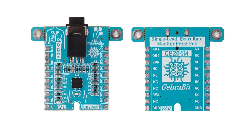
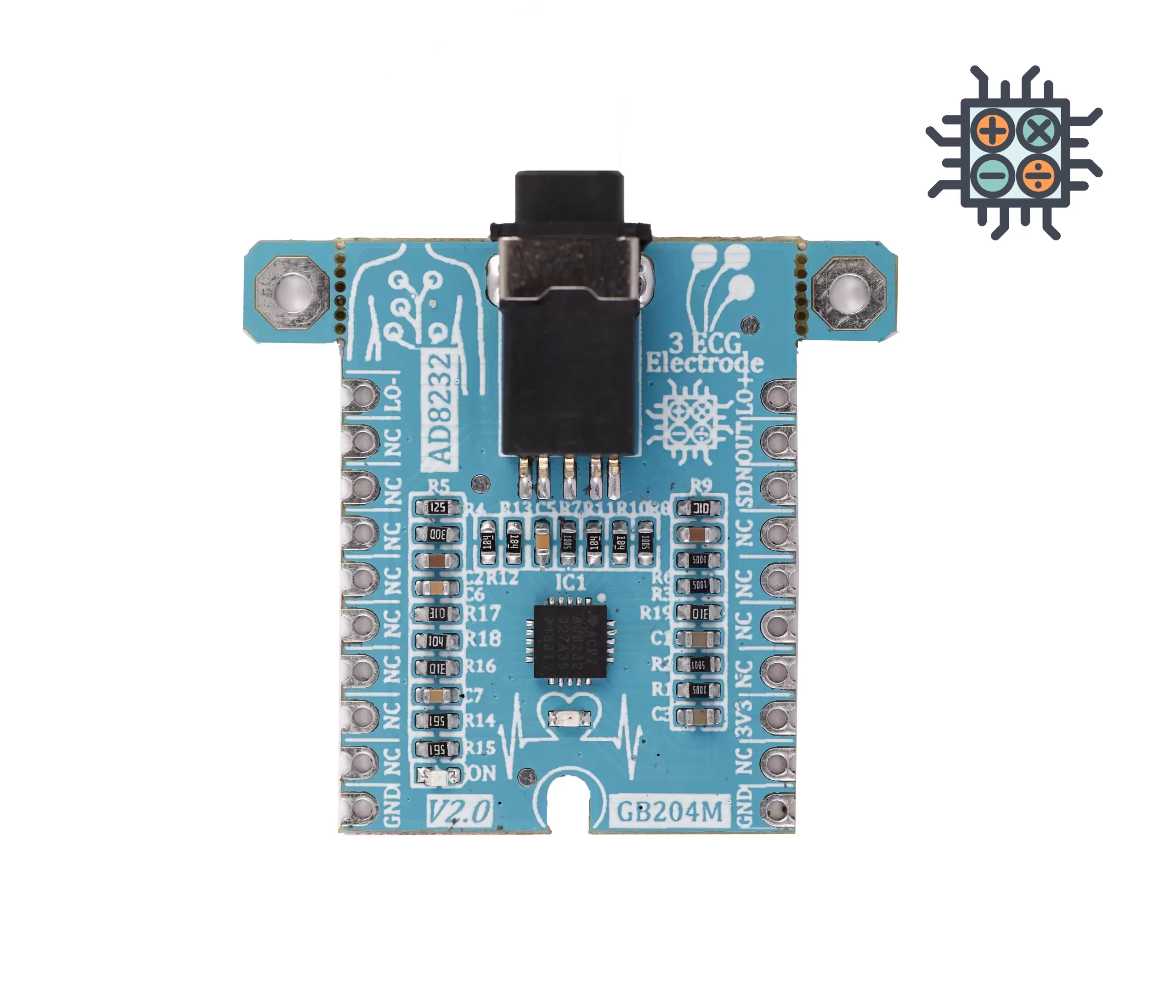
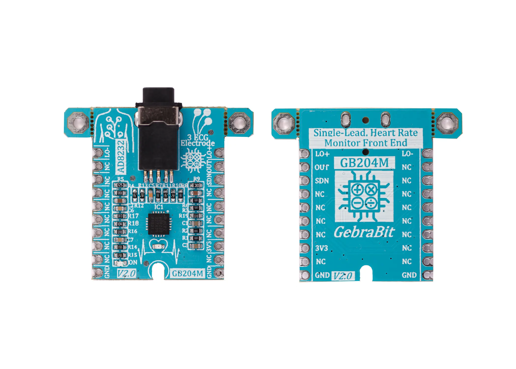
GebraBit AD8232 module

GebraBit AD8232 is a 3 lead, integrated signal conditioning block for ECG and other biopotential measurement module.
GebraBit AD8232 operates with just a “3V3” input Supply Voltage and benefits from AD8232 integrated ECG signal conditioning block. For this reason, a 3.5mm headphone jack female socket is considered. This means any 3-lead ECG cable with a 3.5mm male phone jack can meet our requirements.
The user needs a starter circuit and driver for hardware development and of course software development of the sensor. For the convenience of users, this work has been done by implementing the AD8232 sensor circuit and providing access to the communication and power supply signal pins by GebraBit team.

It is enough to put the GebraBit AD8232 module in the BreadBoard, then by applying the proper voltage, start the GebraBit AD8232 module with any of the Arduino, Raspberry Pi, Discovery boards, and especially we recommend using GebraBit microcontroller development modules to develop the sensor and receive data.

The reason for our recommendation when setting up the GebraBit AD8232 module with GebraBit microcontroller development modules (such as GebraBit STM32F303 or GebraBit ATMEGA32), is the presence of an internal 3V3 regulator on these modules and the compatibility of the pin order of all GebraBit modules together (GEBRABUS standard). It’s enough to put the GebraBit AD8232 module in the corresponding socket as shown in the above picture and develop the desired sensor module without the need for wiring.
Introduction of module sections

AD8232 sensor
It’s the main IC of the following module, which is placed in the center of the module and is in charge of ECG and other biopotential measurement.

3.5mm headphone jack
This headphone jack is installed on the module in order to connect the ECG leads to the module and receive heartbeat signals.

Any 3-lead ECG cable with a 3.5mm male phone jack can be used to connect the device to the body. In most three-lead ECG cables, the leads are red, green, and yellow. The red lead is connected to the right hand, the yellow lead is connected to the left hand, and the green lead is connected to the right leg of the person.

By connecting the male headphone jack of the ECG cable to the corresponding socket on the module and correctly sticking the leads to the body, the module is activated.

The output signal, in terms of shape, cleanliness and voltage level, is similar to the sample signal in the below pic.

heart rate LED
This LED blinks when electrical activity is detected. When the reading is reasonably stable, the LED will flash with your heart rate and can be used as a general indicator of whether your device is receiving electrical signals.

power supply LED
By applying voltage to the module via the corresponding pin, this LED will be lit.

GebraBit AD8232 Module pins

Supply pins
- 3V3: This pin can provide the main power supply of the sensor .
- GND: This is the common ground pin for power the module.

input/output pins
SDN: Shutdown Control Input. Drive SDN low to enter the low power shutdown mode.
LO- : Leads Off Comparator Output. In dc leads off detection mode, LOD− is high when the electrode to −IN is disconnected, and it is low when connected. In ac leads off detection mode, LOD− is always low.
LO+ : Leads Off Comparator Output. In dc leads off detection mode, LOD+ is high when the +IN electrode is disconnected, and it is low when connected. In ac leads off detection mode, LOD+ is high when either the –IN or +IN electrode is disconnected, and it is low when both electrodes are connected.
OUT : Operational Amplifier Output. The fully conditioned heart rate signal is present at this output. OUT can be connected to the input of an ADC.

Connect to the processor

connect to GebraBit STM32F303 and ATMEGA32A
Considering that the analog output pin of the GebraBit AD8232 is based on the GEBRABUS standard and correspond to the ADC pins of the GEBRABIT STM32F303 and GebraBit ATMEGA32A modules, the GebraBit AD8232 module can be placed pin to pin on the GebraBit ATMEGA32A and GEBRABIT STM32F303 modules to receive the analog output data.
Here for better understanding the separate connection of these modules is shown.


connect to ARDUINO UNO
follow the below steps to connect the GebraBit AD8232 module to the ARDUINO UNO:
- Connect the “3V3” pin of the AD8232 module to the “3V3” output pin of the ARDUINO UNO board. (red wire)
Connect the “GND” pin of the AD8232 module to the “GND” pin of the ARDUINO UNO board (black wire).
- Connect the “LO-“, “LO+” and “SDN” pins, which are the AD8232 module digital pins, to the digital pins of the ARDUINO UNO board (for example, D9, D10 and D11 pins). (yellow, orange and green wires)
- Connect the “OUT” pin of the AD8232 module, which is the AD8232 module analog pin, to one of the analog pins of the ARDUINO UNO board (for example, A1 pin). (blue wire)
You can see how to connect the above mentioned steps in this picture:

