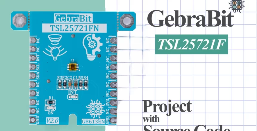
What's the purpose of this project?
The purpose of this project is to interface the TSL2572 ambient light sensor with an Arduino to measure and monitor light intensity in various environments. The sensor can detect ambient light levels and provide accurate lux values, making it ideal for applications such as automatic lighting control, screen brightness adjustments, and environmental monitoring. By reading light levels in real-time, users can develop systems that adapt to changing light conditions, improving energy efficiency and usability.
What are we going to learn in this tutorial?
In this tutorial, you’ll learn how to:
- Connect the TSL2572 sensor to Arduino and establish I2C communication.
- Utilize an existing library for seamless integration, enhancing your understanding of I2C data handling.
- Read ambient light levels in lux using the TSL2572, and interpret the data for real-world applications.
- Implement sensor-based projects for automated lighting and environmental monitoring, developing practical skills to create responsive systems based on light intensity measurements.
This hands-on guide provides valuable insights into sensor integration and real-time data monitoring with Arduino.
What do we need to start this project?
As you probably know, we need some hardware and software to do this project. The titles of these hardware and software are provided to you in the table below and you can prepare/download by clicking on each of them and get ready to start.
|
Required hardware
|
Required software
|
|---|---|
|
Arduino UNO
|
|
First as shown in the image below, we connect the GebraBit TSL2572 module to the Arduino UNO as follows:

Then download and add the GebraBit TSL2572 library to your Arduino IDE.
|
Required Library
|
|---|
If you don’t know how to add GebraBit libraries to Arduino IDE, refer to the tutorial link below.
TSL25721 library and driver
In addition to the modular design of various sensors and ICs, GebraBit tries to provide variety of structured and hardware-independent libraries in C language for the ease of users in setting up and developing software.
For this purpose, after preparing each GebraBit module, the users can refer to the “tutorial” section of the desired module and download the dedicated library, which contains the “ .h” and “ .c” file (Header and Source) and a sample training program under “GebraBit STM32F303”, “GebraBit ATMEGA32A” or “Arduino” development boards.
All the defined functions and structures in the library are commented in full detail and all the received parameters in the arguments of the functions and their return values, are briefly explained. Since the libraries are hardware independed, the user can easily add the library in any of their favorite compilers and develop it by desired microcontroller and development board.
GebraBit_TSL25721.h header file
In this file, based on the datasheet of the sensor or IC, all address registers, the values of each register are defined in the form of “Enumeration”. Also, the casing of the TSL25721 sensor and the configurations related to each of the TSL25721 sensor internal blocks are defined in the form of a “STRUCT” with the name GebraBit_TSL25721 Finally, in the Debug Session environment, all the configurations related to each block can be seen in real time.
USER REGISTER MAP
The registry map or sensor commands are defined in this section:
					/************************************************
 *              USER REGISTER MAP               *
 ***********************************************/
#define TSL25721_ADDRESS               0x39
#define TSL25721_ENABLE                0x00
#define TSL25721_ATIME                 0x01
#define TSL25721_WTIME                 0x03
#define TSL25721_AILTL                 0x04
#define TSL25721_AILTH                 0x05
#define TSL25721_AIHTL                 0x06
#define TSL25721_AIHTH                 0x07
#define TSL25721_PERS                  0x0C
#define TSL25721_CONFIG                0x0D
#define TSL25721_CONTROL               0x0F
#define TSL25721_ID                    0x12
#define TSL25721_STATUS                0x13
#define TSL25721_C0DATA                0x14
#define TSL25721_C0DATAH               0x15
#define TSL25721_C1DATA                0x16
#define TSL25721_C1DATAH               0x17
#define TSL25721_ALS_INTERRUPT_CLEAR   0xE6
#define GLASS_ATTENUATION              1.0f  // 1 because in open air
/*----------------------------------------------*
 *           USER REGISTER MAP End              *
 *----------------------------------------------*/
TSL25721_Ability Enum
This enum is used to activate and deactivate different parts of the sensor:
					typedef enum ALS_Mode
{
	STANDBY = 0 ,
	ACTIVE
}LTR303ALS_ALS_Mode;
TSL25721_Reset_Status Enum
By using this enum, the sensor reset status is determined:
					typedef enum
{
	FAILED = 0 ,
	DONE
}TSL25721 _Reset_Status;
TSL25721_ALS_Mode Enum
Using this enum, the working mode of the sensor is selected:
					1. typedef enum ALS_Mode
2. {
3. 	STANDBY = 0 ,
4. 	ACTIVE
5. }TSL25721_ALS_Mode;
6.
TSL25721_ALS_Gain Enum
The values of this enum are used to set the sensor gain:
					1. typedef enum ALS_Gain
2. {
3.   ALS_GAIN_1X   = 0 ,
4.   ALS_GAIN_8X   = 1 ,
5.   ALS_GAIN_16X  = 2 ,
6.   ALS_GAIN_120X = 3
7. } TSL25721_ALS_Gain;
8.
TSL25721_ Integration_Time Enum
The values of this enum are used to select the values of sensor data Integration time:
					1. typedef enum Integration_Time
2. {
3.   _2P73_mS_INTEGRATION_TIME = 0xFF ,
4.   _27P3_mS_INTEGRATION_TIME = 0xF6 ,
5.   _101_mS_INTEGRATION_TIME  = 0xDB ,
6.   _175_mS_INTEGRATION_TIME  = 0xC0 ,
7.   _699_mS_INTEGRATION_TIME  = 0x00
8. } TSL25721_Integration_Time;
9.
TSL25721_ Measurement_Rate Enum
The measurement rate of sensor data values determined by this enum values:
					1. typedef enum Measurement_Rate
 2. {
 4.   ALS_MEASRATE_50_mS  ,
 5.   ALS_MEASRATE_100_mS ,
 6.   ALS_MEASRATE_200_mS ,
 7.   ALS_MEASRATE_500_mS ,
 8.   ALS_MEASRATE_1000_mS,
 9.   ALS_MEASRATE_2000_mS,
10. } TSL25721 _Measurement_Rate;
11.
TSL25721_ Data_Status Enum
The values of this enum determine whether the read data is new or old values:
					typedef enum Data_Status
{
	OLD_DATA = 0 ,
	NEW_DATA
}TSL25721 _Data_Status;
TSL25721_ Interrupt_Status Enum
The values of this enum are used to inform about the interruption in the sensor:
					1. typedef enum Interrupt_Status
2. {
3. 	INTERRUPT_INACTIVE = 0 ,
4. 	INTERRUPT_ACTIVE
5. }TSL25721_Interrupt_Status;
6.
TSL25721_Data_Valid Enum
The correctness of the sensor data is determined using the values of this enum:
					1. typedef enum Data_Valid
2. {
3. 	DATA_IS_INVALID = 0 ,
4. 	DATA_IS_VALID
5. }TSL25721_Data_Valid;
6.
TSL25721_Interrupt_Persist Enum
Using this enum, it is determined after how many repetitions of a mode, the interrupt should occur:
					1. typedef enum Interrupt_Persist
 2. {
 3.     EVERY_ALS_CYCLE,
 4.     CONSECUTIVE_1_ALS_VALUE_OUT_OF_THR_RANGE,
 5.     CONSECUTIVE_2_ALS_VALUE_OUT_OF_THR_RANGE,
 6.     CONSECUTIVE_3_ALS_VALUE_OUT_OF_THR_RANGE,
 7.     CONSECUTIVE_5_ALS_VALUE_OUT_OF_THR_RANGE,
 8.     CONSECUTIVE_10_ALS_VALUE_OUT_OF_THR_RANGE,
 9. 	CONSECUTIVE_15_ALS_VALUE_OUT_OF_THR_RANGE,
10. 	CONSECUTIVE_20_ALS_VALUE_OUT_OF_THR_RANGE,
11. 	CONSECUTIVE_25_ALS_VALUE_OUT_OF_THR_RANGE,
12. 	CONSECUTIVE_30_ALS_VALUE_OUT_OF_THR_RANGE,
13. 	CONSECUTIVE_35_ALS_VALUE_OUT_OF_THR_RANGE,
14. 	CONSECUTIVE_40_ALS_VALUE_OUT_OF_THR_RANGE,
15. 	CONSECUTIVE_45_ALS_VALUE_OUT_OF_THR_RANGE,
16. 	CONSECUTIVE_50_ALS_VALUE_OUT_OF_THR_RANGE,
17. 	CONSECUTIVE_55_ALS_VALUE_OUT_OF_THR_RANGE,
18. 	CONSECUTIVE_60_ALS_VALUE_OUT_OF_THR_RANGE,
19. } TSL25721_Interrupt_Persistence;
20.
TSL25721 struct
					1. typedef	struct TSL25721
 2. {
 3. 	  uint8_t                         Register_Cache;
 4. 	  uint8_t			              PART_ID;
 5. 	  TSL25721_Ability 				  ALS;
 6. 	  TSL25721_Ability                OSCILLATOR;
 7. 	  TSL25721_Ability 				  WAIT_TIMER;
 8. 	  TSL25721_Ability	              WAIT_LONG_12X;
 9. 	  float				              WAIT_TIME_mS;
10. 	  uint8_t						  WAIT_TIME;
11. 	  float				              WAIT_TIME_STEP;
12. 	  TSL25721_Ability                INTERRUPT;
13. 	  TSL25721_Ability			      SLEEP_AFTER_INTERRUPT;
14. 	  float							  INTEGRATION_TIME_mS;
15. 	  uint8_t						  INTEGRATION_TIME;
16. 	  float				              INTEGRATION_TIME_STEP;
17. 	  TSL25721_Ability                ALS_GAIN_0P16_SCALE;
18. 	  TSL25721_ALS_Gain               ALS_GAIN;
19. 	  float		 					  ALS_GAIN_VALUE;
20. 	  uint8_t			              STATUS_VALUE;
21.       TSL25721_Interrupt_Status		  INTERRRUPT_STATUS;
22.       TSL25721_Data_Valid             DATA;
23.       TSL25721_Interrupt_Persistence  INTERRUPT_PERSISTENCE;
24. 	  uint16_t                        INTERRUPT_LOW_THRESHOLD;
25. 	  uint16_t                        INTERRUPT_HIGH_THRESHOLD;
26. 	  uint8_t 						  ADC_DATA[ADC_DATA_BUFFER_SIZE];
27. 	  uint16_t                        ALS_DATA_CH0;//Reference to uint16_t where visible+IR data will be stored
28. 	  uint16_t               		  ALS_DATA_CH1;//Reference to uint16_t where IR-only data will be stored
29. 	  float      					  COUNTER_PER_LUX;
30. 	  double 			              ALS_LUX;
31. }GebraBit_TSL25721;
32.
Declaration of functions
At the end of this file, all the functions for reading and writing in TSL25721 registers, sensor configuration and receiving data from the sensor are declared:
					1. extern void GB_TSL25721_Read_Reg_Data(uint8_t regAddr,  uint8_t *data)	;
 2. extern void GB_TSL25721_Burst_Read(uint8_t regAddr,  uint8_t *data, uint16_t byteQuantity);
 3. extern void GB_TSL25721_Read_Reg_Bits (uint8_t regAddr, uint8_t start_bit, uint8_t len, uint8_t* data);
 4. extern void GB_TSL25721_Write_Command( uint8_t cmd);
 5. extern void GB_TSL25721_Write_Reg_Data(uint8_t regAddr,  uint8_t data)	;
 6. extern void GB_TSL25721_Burst_Write(uint8_t regAddr,  uint8_t *data, uint16_t byteQuantity)								;
 7. extern void GB_TSL25721_Write_Reg_Bits(uint8_t regAddr, uint8_t start_bit, uint8_t len, uint8_t data);
 8. /********************************************************
 9.  *       Declare TSL25721 Configuration Functions         *
10.  ********************************************************/
11. extern void GB_TSL25721_Internal_Oscillator ( GebraBit_TSL25721 * TSL25721 , TSL25721_Ability osc )  ;
12. extern void GB_TSL25721_ALS ( GebraBit_TSL25721 * TSL25721 , TSL25721_Ability als )  ;
13. extern void GB_TSL25721_Interrupt ( GebraBit_TSL25721 * TSL25721 , TSL25721_Ability intr )  ;
14. extern void GB_TSL25721_Clear_Interrupt ( GebraBit_TSL25721 * TSL25721 )  ;
15. extern void GB_TSL25721_Sleep_After_Interrupt ( GebraBit_TSL25721 * TSL25721 , TSL25721_Ability intafs )  ;
16. extern void GB_TSL25721_Wait_Timer ( GebraBit_TSL25721 * TSL25721 , TSL25721_Ability timer ) ;
17. extern void GB_TSL25721_Integration_Time  (GebraBit_TSL25721 * TSL25721 ,float time ) ;
18. extern void GB_TSL25721_Wait_Long_12x ( GebraBit_TSL25721 * TSL25721 , TSL25721_Ability wlong )  ;
19. extern void GB_TSL25721_Check_Wait_Long_12x ( GebraBit_TSL25721 * TSL25721  )   ;
20. extern void GB_TSL25721_Set_Wait_Time ( GebraBit_TSL25721 * TSL25721 , float wait  );
21. extern void GB_TSL25721_ALS_Gain_0p16_Scale ( GebraBit_TSL25721 * TSL25721 , TSL25721_Ability scale )  ;
22. extern void GB_TSL25721_Check_ALS_Gain_0p16_Scale( GebraBit_TSL25721 * TSL25721  ) ;
23. extern void GB_TSL25721_ALS_Gain ( GebraBit_TSL25721 * TSL25721 , TSL25721_ALS_Gain gain );
24. extern void GB_TSL25721_Read_Part_ID ( GebraBit_TSL25721 * TSL25721  );
25. extern void GB_TSL25721_Read_STATUS ( GebraBit_TSL25721 * TSL25721 ) ;
26. extern void GB_TSL25721_Interrupt_Persistence ( GebraBit_TSL25721 * TSL25721 , TSL25721_Interrupt_Persistence persist ) ;
27. extern void GB_TSL25721_Interrupt_Upper_Limitation ( GebraBit_TSL25721 * TSL25721 , uint16_t limit );
28. extern void GB_TSL25721_Interrupt_Lower_Limitation ( GebraBit_TSL25721 * TSL25721 , uint16_t limit )  ;
29. extern void GB_TSL25721_initialize( GebraBit_TSL25721 * TSL25721 )  ;
30. extern void GB_TSL25721_Configuration(GebraBit_TSL25721 * TSL25721)  ;
31. extern void GB_TSL25721_Read_CH0_CH1_Raw_Data(GebraBit_TSL25721 * TSL25721);
32. extern void GB_TSL25721_Lux_Reading(GebraBit_TSL25721 * TSL25721);
33. extern void GB_TSL25721_Get_Data(GebraBit_TSL25721 * TSL25721);
34.
GebraBit_TSL25721.c source file
In this file, which is written in C language, all the functions are commented in full detail, and all the parameters received in the arguments of the functions and their return values are clearly explained so we confine to these explanations and invite users to check this file directly for more information.

Sample program in Arduino
After connecting the module to Arduino and adding the library to the IDE, go to the following path: File > Examples > GebraBit_TSL2572 > Luminosity
Description of Sample file
Enums and functions required by GebraBit TSL25721 module have been added to the structures. In the next part, a variable named TSL25721_Module of the GebraBit_TSL25721 structure type (this structure is in the GebraBit_TSL25721 header and is explained in the GebraBit_TSL25721 library description section) is defined for the configuration of the GebraBit TSL25721 module:
GebraBit_TSL25721 TSL25721;
In the next part of the written code, using the GB_TSL25721_initialize (&TSL25721 _Module) and GB_TSL25721_Configuration (&TSL25721_Module) functions, we set the GebraBit TSL25721 module and finally, in the while part of the program, the data is read from the sensor and the ALS and CLEAR values are continuously received:
					void setup() {
    Wire.begin();           // Initialize the I2C bus
    Serial.begin(9600);     // Initialize serial communication for debugging

    GB_TSL25721_initialize(&TSL25721); // Initialize the TSL25721 sensor
    GB_TSL25721_Configuration(&TSL25721); // Configure the TSL25721 sensor
}

void loop() {
    GB_TSL25721_Get_Data(&TSL25721); // Read data from the sensor

    Serial.print("luminosity: ");
    Serial.print(TSL25721.ALS_LUX);
    Serial.println(" lx");

    delay(2000); // Delay between readings
}
The Sample file code text:
					#include "GebraBit_TSL25721.h"

GebraBit_TSL25721 TSL25721;

void setup() {
    Wire.begin();           // Initialize the I2C bus
    Serial.begin(9600);     // Initialize serial communication for debugging

    GB_TSL25721_initialize(&TSL25721); // Initialize the TSL25721 sensor
    GB_TSL25721_Configuration(&TSL25721); // Configure the TSL25721 sensor
}

void loop() {
    GB_TSL25721_Get_Data(&TSL25721); // Read data from the sensor

    Serial.print("luminosity: ");
    Serial.print(TSL25721.ALS_LUX);
    Serial.println(" lx");

    delay(2000); // Delay between readings
}
Connect your arduino to computer and select your Arduino Board

Then Verify and Upload the Sample code

After uploading the code, open the serial monitor and you can see the luminosity values.


In the following, you can download the GebraBit_TSL2572 Library, the schematic of the modules and the “TSL2572 datasheet”.
Program output video
The video of the module operation will be uploaded soon

