OVERVIEW
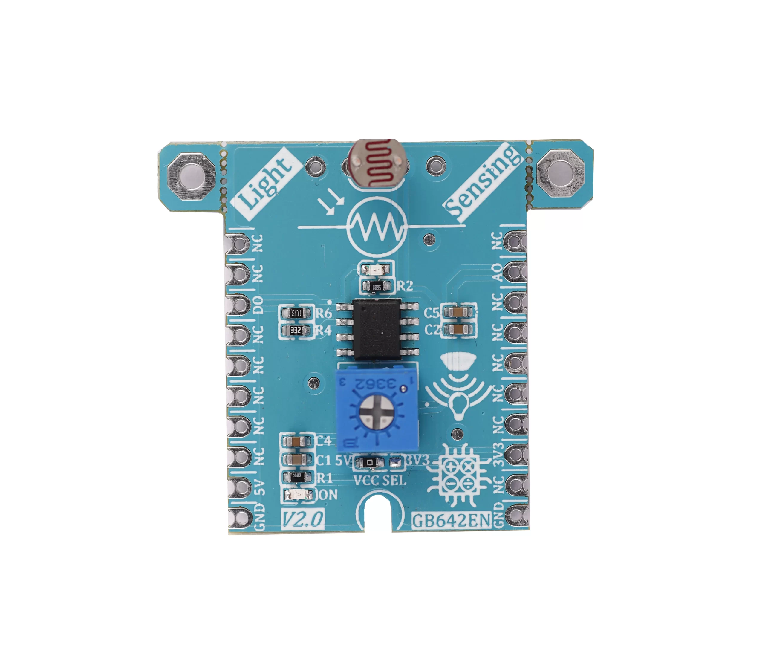
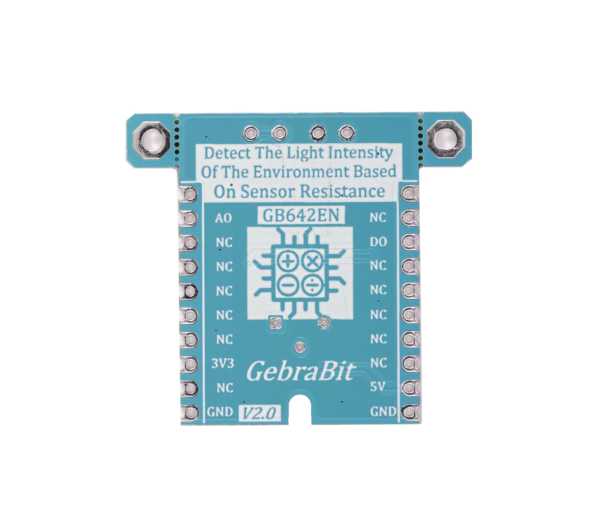
GebraBit Light Sensing module is a light-dependent resistor integrated with a Voltage Comparator OpAmp.
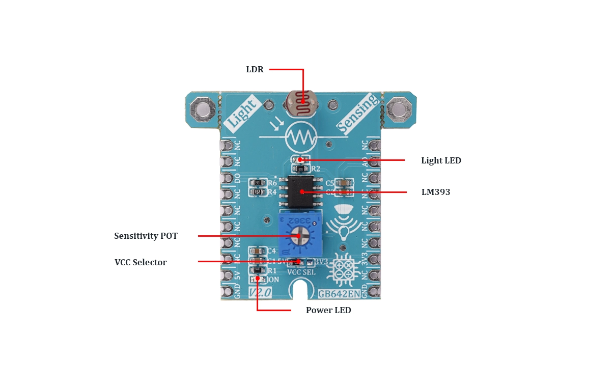
GebraBit Light Sensing module can operate with “3V3” or “5V” supply Voltages by considered “VCC SEL” jumper selector.
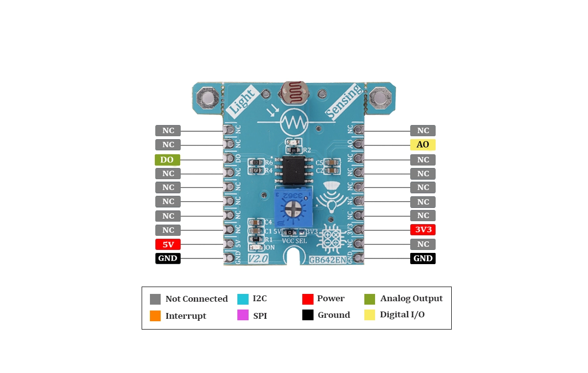
Module output data is available as the analog and digital voltage on GebraBit Light Sensing module “A0” and “D0” pins.
The light intensity threshold is adjustable by an embedded potentiometer in the GebraBit Light Sensing module, when the light intensity goes above, or below the threshold, the “DO” pin and the “Light Detected” LED status will be changed.
The working principle of an LDR is photoconductivity, which is nothing but an optical phenomenon. When the light is absorbed by the material then the conductivity of the material enhances. When the light falls on the LDR, then the electrons in the valence band of the material are eager to the conduction band. But, the photons in the incident light must have energy superior to the bandgap of the material to make the electrons jump from one band to another band (valance to conduction).
Hence, when light has ample energy, more electrons are excited to the conduction band which grades in a large number of charge carriers. When the effect of this process and the flow of the current starts flowing more, the resistance of the device decreases.
WARNING: FOR ACCURATE INFORMATION ABOUT ICs ABSOLUTE MAXIMUM RATINGS AND ITS PRECIOUS CHARACTERISTICS RANGES, USERS MUST CERTAINLY REFER TO ICs MANUFACTURE DATASHEET.
Key Features
- User-selectable module power supply voltage between 3V3 and 5V
- Built-in voltage comparator
- Analog Voltage OUTPUT
- Digital Voltage OUTPUT
- Adjustable light intensity threshold
- On Board, ON/OFF LED indicator
- Pin Compatible with GEBRABUS
- GebraBit small package
- It can be used as a daughter board of GebraBit MCU Modules
- Featuring Castellated pad (Assembled as SMD Part)
- Separatable screw parts to reduce the size of the board
Pinout Diagram

Module Overview

Documents Link
Project and Source Code

Schematic (.Pdf)

Module Layout (.Pdf)

Datasheet

Module Overview


