GebraBit

GebraBit Light sensing Module Overview

متن سربرگ خود را وارد کنید

GebraBit Light Sensing

GebraBit Light sensing Module Overview

GebraBit Light Sensing
  1. Home
  2. »
  3. Blog
  4. »
  5. GebraBit Light sensing Module Overview

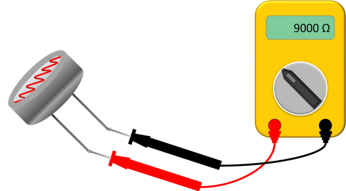
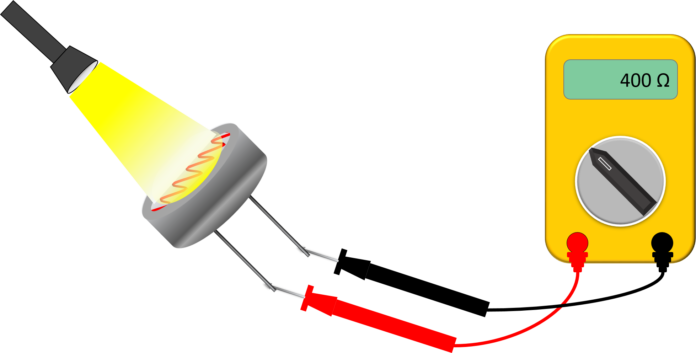
LDR (Light Dependent Resistor) as the name states is a special type of resistor that works on the photoconductivity principle means that resistance changes according to the intensity of light. Its resistance decreases with an increase in the intensity of light.

LDRs are made from semiconductor materials to enable them to have their light sensitive properties.

Although a semiconductor material is used for these photoresistors, they are purely passive devices because they do not possess a PN junction, and this separates them from other photodetectors like photodiodes and phototransistors.

GebraBit LDR module

GebraBit Light Sensing

The GebraBit Light Sensing module is a resistive light intensity detector, with a wavelength  range of 400 to 800 nm and an analog-voltage/digital-logic(0 or 1) output, the analog output changes according to the light intensity. GebraBit Light Sensing module is a light-dependent resistor integrated with a Voltage Comparator OpAmp and can operate with “3V3” or “5V” supply Voltages by considered “VCC SEL” selector jumper.GebraBit has designed this module to use this sensor and read the values of ambient light changes using LDR sensors.

Module output data is available as the analog and digital voltage on the GebraBit Light Sensing module “A0” and “D0” pins.

Both large size LDR and small size LDR can be used on GebraBit Light Sensing.

GebraBit Light Sensing

To start this module, just put the GebraBit Light Sensing module on the BreadBoard, then start the module by applying the proper voltage. Now you can Set-up the GebraBit Light Sensing module with any of Arduino, Raspberry Pi, Discovery board, and receive the data. We especially recommend you to use GebraBit microcontroller modules ( GebraBit STM32F303 or GebraBit ATMEGA32 module) for developing GebraBit Light Sensing.

The reason of our recommendation for setting-up the GebraBit Light Sensing module with GebraBit microcontroller development modules(such as GebraBit STM32F303 or GebraBit ATMEGA32), is the presence of an internal 3V3 regulator on these modules and the compatibility of the pin order of all GebraBit modules together (GEBRABUS standard).To set-up the module with GebraBit microcontrollers, it’s enough to Put the GebraBit Light Sensing module on the GebraBit STM32F303 or GebraBit ATMEGA32 as pin to pin and then start the module by applying a proper voltage.

Module Specification

Module Application

  • Module type: Resistance light Sensing module
  • Module Supply Voltage: 3.3 V or 5 V
  • Output Type: Analog-Voltage / Digital-Logic
  • Wavelength Range: 400 to 800 nm
  • Peak Wavelength : 540nmn -560 nm
  • Module Current Consumption : 10 mA to 30 mA (Typ. 20 mA)
  • Robotic

Module Key Features

  • User-selectable module power supply voltage between 3V3 and 5V
  • Built-in voltage comparator
  • Analog Voltage OUTPUT
  • Digital Voltage OUTPUT
  • Adjustable light intensity threshold
  • On Board, ON/OFF LED indicator
  • Pin Compatible with GEBRABUS
  • It can be used as a daughter board of GebraBit MCU Modules
  • Featuring Castellated pad (Assembled as SMD Part)
  • Separatable screw parts to reduce the size of the board
  • Package: GebraBit small (36.29mm x 32.72mm)

Introduction of module sections

LDR

This is the light-sensitive resistance of this module and its value changes as the light intensity changes.

Users can use both large size LDRs and small size LDRs on the GebraBit Light Sensing module .

sensitivity level potentiometer

The light intensity threshold is adjustable by an embedded potentiometer in the GebraBit Light Sensing module, when the light intensity goes higher or lower than the threshold, the “DO” pin status will be changed.

LM393 Voltage Comparator

It is the main IC of this module and is in charge of  comparing the voltage of the LDR resistor with the threshold value determined by the potentiometer.

“Light Detected” LED

When the light intensity goes higher or lower than the threshold value determined by the potentiometer, the status of the “light detection” LED changes.

VCC Selector Jumper

According to the state of 0R resistance of this jumper, the module main supply voltage is selected between “5V” and “3V3”.

power LED

According to the state of the “VCC SEL” jumper and applying voltage to the module by the corresponding pin, this LED will be lit.

GebraBit LDR Module pins

Supply pins

  • 3V3 and 5V: These pins can provide the main power supply of the module according to the state of the “VCC SEL” Selector Jumper.
  • GND: This is the ground pin of the module.

Output pins

AO: This pin is the module  analog output pin and the module analog data is available through this pin. The output of this pin changes as the intensity and quality of light change.

DO: This pin is the digital output pin of the module and the sensor logical datas(0 and 1) are available to the user through this pin. when the light intensity goes higher or lower than the threshold, the “DO” pin status will change.

In the absence of ambient light situation, “LED” is on and the voltage level of “DO” is 0, and in the presence of ambient light, “LED” is off and the voltage level of “DO” is changed to 5 volts.

Connect to the processor

connect to GebraBit ATMEGA32A and STM32F303

To Set-up the GebraBit Light Sensing with the GebraBit ATMEGA32A or GebraBit STM32F303 you can simply place the GebraBit Light Sensing module pin to pin on the GebraBit ATMEGA32A or GebraBit STM32F303 module and start the module by applying the proper voltage.

Here for better understanding the separate connection of the modules is shown.

You can set-up the GebraBit Light Sensing with the GebraBit STM32F303 module in the same way.

Note: If you are using GebraBit microcontroller modules, note that the “VCC SEL”  jumper of GebraBit Light Sensing module is set to “3V3” so that you can easily get “3V3” voltage from the microcontroller module.

connect to ARDUINO UNO

follow the below steps to connect the GebraBit Light Sensing module to the ARDUINO UNO:

  • Since the “VCC SEL” jumper is set on “3V3”, Connect the “3V3” pin of Light Sensing module to the “3V3” output pin of the ARDUINO UNO board. (red wire)
  • Connect the “GND” pin of the Light Sensing module to the “GND” pin of the ARDUINO UNO board (black wire).
  • Connect the “AO” pin of the Light Sensing module to one of the ARDUINO UNO board “analog” pins (e.g.A0). (yellow wire)
  • Connect the “DO” pin of the Light Sensing module to one of the ARDUINO UNO board “digital” pins (e.g.D9). (blue wire)

این مقاله را با دوستانتان به اشتراک بگذارید!

Leave a Reply

Your email address will not be published. Required fields are marked *

Shopping cart
Start typing to see posts you are looking for.

Sign in

No account yet?