GebraBit

Gebrabit IAM20380 Gyroscope Module Overview

متن سربرگ خود را وارد کنید

BLOG

Gebrabit IAM20380 Gyroscope Module Overview

  1. Home
  2. »
  3. Blog
  4. »
  5. Gebrabit IAM20380 Gyroscope Module Overview

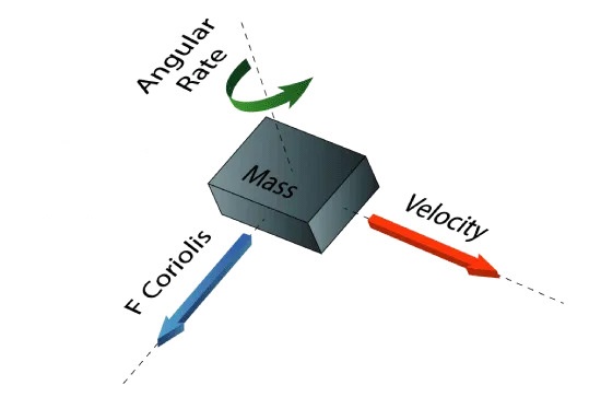
The Gyroscope measures angular velocity using the Coriolis Effect. When a mass moves in a certain direction with a certain speed and an external angular rate is applied as shown in the green arrow below, a force such as the red-blue arrow shown, causes the mass to move vertically.

So, similar to the accelerometer, this displacement causes a change in capacitance that is associated with a specific angular rate.

Gyroscope

The structure of the micro-Gyroscope is something like this. A mass that is constantly moving or oscillating and when an external angular rate is applied, the flexible part of the mass moves and undergoes vertical displacement.

An overview of the IAM20380 gyroscope

IAM20380 gyroscope

The IAM-20380 is a 3-axis Gyroscope in a 16-pin LGA package. The IAM-20380 Gyroscope sensor also has a 512-byte FIFO which can reduce serial bus  traffic and power consumption by allowing the processor to sequentially read sensor data and then go into low-power mode. The IAM-20380 sensor with its 3 integrated axis helps designers to reduce the space required for design and the cost spent on selecting parts. IAM-20380 Gyroscope has a programmable full-scale range of ±250 dps, ±500 dps, ±1000 dps, and ±2000 dps and 16-bit internal ADC, which makes this sensor an ideal choice for applications such as navigation systems, Lift Gate Motion Detections and even camera stabilization. Other advanced features of this sensor include programmable digital filters, internal temperature sensor, and I2C and SPI digital communication protocols.

Specification
Applications
1
Number of Axis: 3-Axis
Navigation systems Aides for Dead Reckoning 
2
Output type: Digital-I2C or SPI
Lift Gate Motion Detections
3
FSR: ±250, ±500, ±1000, ±2000(dps)
Accurate Location for Vehicle to Vehicle and Infrastructure
4
Gyroscope ADC: 16 Bit
360º view camera stabilization
5
Car Alarm
6
Telematics
7
Insurance Vehicle Tracking
**For more specifications, please refer to datasheet**

Specification

Applications

  • Number of Axis: 3-Axis
  • Output type: Digital-I2C or SPI
  • FSR: ±250, ±500, ±1000, ±2000(dps)
  • Gyroscope ADC: 16 Bit

〈 For more specifications, please refer to datasheet 〉

• Navigation systems Aides for Dead Reckoning 

• Lift Gate Motion Detections

• Accurate Location for Vehicle to Vehicle and Infrastructure
•360º view camera stabilization
• Car Alarm
• Telematics
• Insurance Vehicle Tracking

IAM20380 Module Key Features

  • User-selectable module power supply voltage between 1V8 and 3V3
  • User-selectable module I/O logic voltage between 1V8 and 3V3
  • User-selectable interface protocol (I2C or SPI)
  • User-selectable I2C address (AD0)
  • Access to all data pins of the sensor
  • On Board, ON/OFF LED indicator
  • Pin Compatible with GEBRABUS
  • It can be used as a daughter board of GebraBit MCU Modules
  • Featuring Castellated pad (Assembled as SMD Part)
  • Separatable screw parts to reduce the size of the board 
  • Package: GebraBit small (36.29mm x 32.72mm)

GebraBit IAM20380 module

GEBRABIT IAM20380

After the explanations mentioned above, due to the LGA package and the lack of access to the sensor pins, you have noticed that, the user needs a starter circuit and driver for the hardware development and of course the software development of the IAM20380 sensor. For the convenience of users, this work has been done by implementing the IAM20380  sensor circuit and providing access to the communication and power supply signal pins, with the ability to select the I2C or SPI communication protocol and the operation voltage and logic level of the communication protocols.

GEBRABIT IAM20380

It is enough to put the GebraBit IAM20380 module in the BreadBoard, then by applying the proper voltage and choosing the I2C or SPI communication protocol, Set-up the GebraBit IAM20380 module with any of Arduino, Raspberry Pi, Discovery board, and then receive the data. We especially recommend you to use GebraBit microcontroller modules ( GebraBit STM32F303 or GebraBit ATMEGA32 module) for developing GebraBit IAM20380.

The reason of our recommendation for setting-up the GebraBit IAM20380 module with GebraBit microcontroller development modules(such as GebraBit STM32F303 or GebraBit ATMEGA32), is the presence of an internal 3V3 regulator on these modules and the compatibility of the pin order of all GebraBit modules together (GEBRABUS standard), it’s enough to Put the IAM20380 in the corresponding socket as shown in the above picture and develop the desired sensor module without the need for wiring. 

Introduction of IAM20380 module sections

IAM20380 sensor

It’s the main IC of the following module, which is placed in the center of the module and its circuit is designed.

IAM20380 Main IC

Communication protocol selection jumpers

If the 0R resistors of all Jumper Selectors are to the left, the I2C protocol is selected.

IAM20380 I2C

If the 0R resistors of all Jumper Selectors are to the right, the SPI protocol is selected.

By default, the I2C protocol is selected.

AD0 SEL Jumper

If the I2C protocol is selected, the state of the AD0 SEL jumper, determines the I2C address of the sensor (0 => 0x68 or  1 =>0x69).

By default, the 0R resistor is set to 0 and the address 0x68 is selected.

VDIO SEL Jumper

According to the state of 0R resistance of this jumper, the logic level of digital communication (I2C or SPI) of the sensor is selected between 1V8 and 3V3.

By default, the digital communication logic level (I2C or SPI) of the sensor is selected 3V3

VDD SEL Jumper

According to the state of 0R resistance of this jumper, the main voltage of the sensor power supply is selected between 1V8 and 3V3.                                                                

IAM20380 VDD

By default, the main sensor supply voltage is 3V3.

LED power supply

According to the state of the VDD SEL jumper and applying voltage to the module by the corresponding pin, the LED of the module will be lit.

IAM20380 LED

GebraBit IAM20380 Module pins

Supply pins

  • 3V3: This pin can supply the sensor’s main power supply and the logic level of the sensor’s digital connection (I2C or SPI) according to the state of the VDDSEL and VDIOSEL jumper selectors.
  • 1V8: This pin can supply the sensor’s main power supply and the logic level of the sensor’s digital communication (I2C or SPI) according to the state of the VDDSEL and VDIOSEL jumper selectors.

• GND: This is the common ground pin for power and logic level of the sensor.

IAM20380 Pinout POWER

I2C pins

By using the on-board embedded Jumper selectors, you can choose the type of module communication  . If the 0R resistors of all the Jumper Selectors are to the left side, the I2C protocol is selected. AD0 SEL jumper status is the I2C address of the sensor (0x68 or 0x69 ).

  • SDA: This pin is the I2C communication data pin, which is connected to the corresponding data pin in the microcontroller (processor). According to the state of the VDIOSEL jumper, you can use the logic level with a voltage of 1V8 or 3V3.This pin is pulled up with a 10K resistor.
  • SCL: This pin is the I2C communication clock pin, which is connected to the corresponding clock pin in the microcontroller (processor). Depending on the state of the VDIOSEL jumper, you can use the logic level with a voltage of 1V8 or 3V3. This pin is pulled up with a 10K resistor.

SPI pins

The type of connection with the module can be selected using the jumper selectors built on the board. If the 0R resistors of all the jumper selectors are to the right, the SPI protocol has been selected. The state of the AD0 SEL jumper has no effect in this case.

  • SDI (MOSI): This pin is used to send data from the microcontroller (processor) to the module (sensor). The abbreviation of this pin is derived from the Latin phrase Serial Data In / Microcontroller Out Sensor In.
  • SDO (MISO): This pin is used to send data from the module (sensor) to the microcontroller (processor). The abbreviation of this pin is derived from the Latin phrase Serial Data Out / Microcontroller In Sensor Out.
  • SCK: This pin is the clock pin for SPI communication, which is considered as an input for the sensor and is connected to the corresponding clock pin in the microcontroller (processor).
  • CS: This pin is the Chip Select pin for SPI communication with the module (sensor), which is selected by applying LOW voltage (0V), the module (sensor) for SPI communication. This pin is an input pin for the sensor.

If you want to use several GebraBit IAM20380 modules at the same time, it is enough to connect the SDO, SDI, SCK pins of all modules and the microcontroller (processor) and assign a unique pin to each CS.

Other pins

  • INT: Interrupt pin for IAM20380 sensor, according to the datasheet , the user can set the interrupt conditions, the modes and methods of the interruption, etc.
  • FSY(FSYNC): This pin is used to synchronize the sensor with an external source. For more information, read the data sheet of the sensor. By default, this pin is connected to the ground with “R3”resistor. To use Pin, “R3” resistor must be removed(disassembly) from the module.

Connect to the processor

I2C connection with GebraBit STM32F303

First, make sure that the I2C protocol is selected by using the on-board jumpers, then for i2c communication of GebraBit IAM20380 and GebraBit STM32F303 microcontroller module, after defining SDA and SCL on pins PB9 and PB8 (for convenience in STMCUBEMX), follow the below steps:


  • Connect the 3V3 pin of the IAM20380 module to the 3V3 output pin of the microcontroller module. (red wire)
  • Connect the GND pin of the IAM20380 module to the GND pin of the microcontroller module (black wire).
  • Connect the SCL pin of the IAM20380 module to the PB8 pin of the microcontroller (SCL) module (blue wire).

• Connect the SDA pin of the IAM20380 module to the PB9 pin of the microcontroller (SDA) module. (yellow wire)

How to connect the above mentioned steps, can be seen in the below picture:

Note: Considering that the PA14 pin of the GebraBit STM32F303 microcontroller module is used to program the microcontroller, I2C setting on the PA14 and PA15 pins is impossible in this version, so in this version for  I2C  connection with the GebraBit STM32F303 microcontroller module, GebraBit IAM20380 module cannot be placed on it as Pin to Pin. To make a more convenient connection between the two modules, you can select the SPI protocol by using the on-board jumpers and then place the GebraBit IAM20380 module as Pin to Pin on the GebraBit STM32F303 module. 

SPI connection with GebraBit STM32F303

First, make sure that the SPI protocol is selected by using the on-board jumpers, then for connecting GebraBit IAM20380 module to the GebraBit STM32F303 microcontroller module with SPI protocol, after defining SDI, SDO, SCK, and CS on pins PB5, PB4, PB3, and PC13 ( For ease of work in STMCUBEMX) place the GebraBit IAM20380 module Pin to Pin on the GebraBit STM32F303 module easily:

SPI or I2C connection with GebraBit ATMEGA32A

Considering that the SPI and I2C pins of the ATMEGA32A microcontroller are based on the GEBRABUS standard and correspond to the SPI and I2C pins of other GEBRABIT modules, the GebraBit IAM20380 module can be placed pin to pin  on the GebraBit ATMEGA32A module and communicate with the GebraBit IAM20380 module via SPI or I2C by changing the state of the protocol selection jumper resistors:

I2C connection with ARDUINO UNO

First, make sure that the I2C protocol is selected by using the on-board jumpers, then follow the below steps to connect the GebraBit IAM20380 module to the ARDUINO UNO via I2C :

  • Connect the 3V3 pin of the IAM20380 module to the 3V3 output pin of the ARDUINO UNO board. (red wire)

Connect the GND pin of the IAM20380 module to the GND pin of the ARDUINO UNO board (black wire).

  • Connect the SCL pin of the IAM20380 module to the A5 pin of the ARDUINO UNO board (SCL). (blue wire)
  • Connect the SDA pin of the IAM20380 module to the A4 pin of the ARDUINO UNO board (SDA). (orange wire)

How to connect the above mentioned steps, can be seen in this picture:

SPI CONNECTION WITH ARDUINO UNO

First, make sure the SPI protocol is selected using the on-board jumpers, then follow the below  steps to connect the GebraBit IAM20380 module to the ARDUINO UNO via SPI:

  • Connect the 3V3 pin of the IAM20380 module to the 3V3 output pin of the ARDUINO UNO board. (red wire)

Connect the GND pin of the IAM20380 module to the GND pin of the ARDUINO UNO board (black wire).

  • Connect the SDI pin of the IAM20380 module to the D11 pin of the ARDUINO UNO board (SDI). (yellow wire)
  • Connect the SDO pin of the IAM20380 module to the D12 pin of the ARDUINO UNO board (SDO). (Purple wire)
  • Connect the SCK pin of the IAM20380 module to the D13 pin of the ARDUINO UNO board (SCK). (Orange wire)
  • Connect the CS pin of the IAM20380 module to the D10 pin of the ARDUINO UNO board (SS). (blue wire)

How to connect the above mentioned items, can be seen in this picture:

این مقاله را با دوستانتان به اشتراک بگذارید!

Leave a Reply

Your email address will not be published. Required fields are marked *

Shopping cart
Start typing to see posts you are looking for.

Sign in

No account yet?