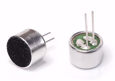
Condenser Microphone
The microphone is a transducer device which converts sound energy into electrical energy. Microphones are often referred to a MIC. A microphone is used to capture some sort of sound and produce an electrical signal according to it.
A microphone has a sensitive component which converts the air pressure variations created by the sound wave into electrical signal. Depending on this component and the method to convert the sound wave into Electrical signal, there are various type microphones are available in the electronics and sound engineering field. Most common types are Dynamic Microphones, Condenser Microphone, Piezo electrical microphone etc.
The microphone generates the input for the sound sensor module and consists of a thin diaphragm that is one plate of a capacitor. The second plate of the capacitor is the back plate and in parallel to the diaphragm in very close distance. The following picture shows a basic schematic of the microphone.
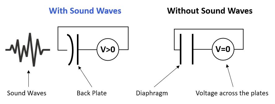
If someone speaks into the microphone, the sound waves created by the voice hit the diaphragm. Due to those hits, the diaphragm vibrates and therefore the distance between the two plates of the capacitor gets shorter or wider (picture on the left side).
Because the capacitance is directly proportional to the distance between the plates, the sound waves of the voice changes the voltage across the plates that has a direct influence of the circuit of the sensor module.
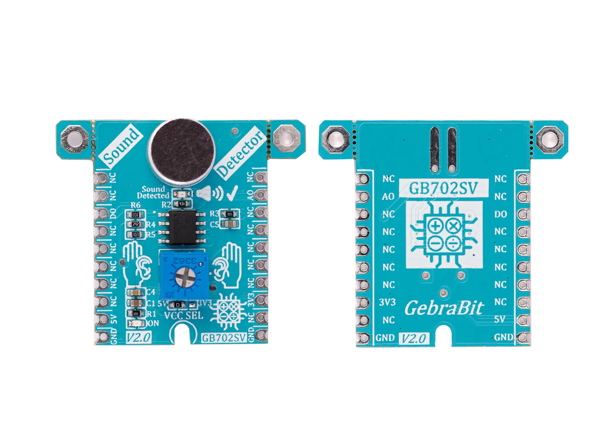
sound detector module
The sound sensor is a module that monitors and detects the sound signals like voice, claps, snaps, knocks, etc. It is also known as an acoustic sensor or sound detector. Used in various applications such as security systems, monitoring systems, radios, telephones, mobile phones, computers, home automation systems, consumer electronic appliances, etc.
Sound detection sensor works similarly to our Ears, having diaphragm which converts vibration into signals. However, what’s different as that a sound sensor consists of an in-built capacitive microphone, peak detector and an amplifier (LM386, LM393, etc.) that’s highly sensitive to sound.
It contains a microphone, power amplifier, and output actuator. The microphone that acts as an input sensor receives the sound signal and converts it into an electrical signal. Then this signal is amplified by the power amplifier and its amplitude is detected by the peak detector. The output actuator, like a loudspeaker, converts this amplified electrical signal into a sound signal for listening.