GebraBit

GebraBit LED Module Overview

متن سربرگ خود را وارد کنید

GEBRABIT LED

GebraBit LED Module Overview

GEBRABIT LED
  1. Home
  2. »
  3. Blog
  4. »
  5. GebraBit LED Module Overview

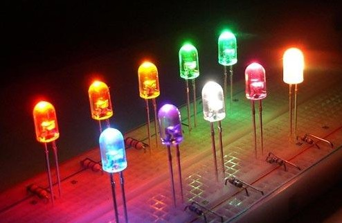
A Light Emitting Diode (LED) is a semiconductor device, which can emit light when an electric current passes through it. To do this, holes from p-type semiconductors recombine with electrons from n-type semiconductors to produce light. The wavelength of the light emitted depends on the bandgap of the semiconductor material. Harder materials with stronger molecular bonds generally have wider bandgaps.

GebraBit LED module

GEBRABIT LED

GebraBit LED module features either SMD or DIP triple LEDs.Note that avoid using DIP and SMD simultaneously. For proper operation, either DIP or  SMD LEDs must be assembled. GebraBit LED module can operate with “3V3” or “5V” supply Voltages.

For easy accessibility, GebraBit LED  gives access to the “LD1“, “LD2“, “LD3“, “VCC“, and “GND” pins by a 5-pin PH connector to extend them on other boards.

To start this module, just put the GebraBit LED module in the BreadBoard, then start the module by applying the proper voltage. Due to the compatibility of the GebraBit LED pins with the GebraBus standard,we recommend using GebraBit microcontroller development modules for testing and commissioning. To fulfill this aim, it’s enough to set the GPIO pins of the microcontroller which are corresponding to the LD1, LD2, LD3 pins as the output pins and change the output voltage level.

Module Specification

Module Application

  • Module type: LED MODULE
  • LEDs: 3 Different DIP/SMD
  • Module Supply Voltage: 3.3 V or 5.0 V
  • Module Logic Voltage : 3.3 V or 5.0 V
  • Module Current Consumption : 10 mA to 50 mA (Typ. 30 mA)
  • Robotic

Module Key Features

  • Features either SMD or DIP triple LEDs
  • User-selectable module power supply voltage between 3V3 and 5V
  • Control Pin access with PH connector
  • On Board, ON/OFF LED indicator
  • Pin Compatible with GEBRABUS
  • It can be used as a daughter board of GebraBit MCU Modules
  • Featuring Castellated pad (Assembled as SMD Part)
  • Separatable screw parts to reduce the size of the board
  • Package: GebraBit small (36.29mm x 32.72mm)

Introduction of module sections

LEDs

Users can use both DIP and SMD LEDs on the GebraBit LED module. But please Note that avoid using DIP and SMD simultaneously.

Signal ports

For easy accessibility, the GebraBit LED  gives access to the “LD1“, “LD2“, “LD3“, “VCC“, and “GND” pins by a 5-pin PH connector . Users can access  to these pins by connecting a proper female PH connector to this connector and extended the GebraBit LED  to other boards and enabled LEDs easily.

VCC SEL jumper

According to the state of 0R resistance of this jumper, the module main supply voltage is selected between “5V” and “3V3”.

GebraBit LED Module pins

Supply pins

  • 3V3 and 5V: These pins can provide the main power supply of the module according to the state of the “VCC SEL” Selector Jumper.
  • GND: This is the ground pin of the module.

LED pins

LD1 and LD2 and LD3:These three pins, which are embedded on both the right and left sides of the module, are the LED pins of the module and can be used to access and control the LEDs.

Connect to the processor

Connect to GebraBit ATMEGA32A and STM32F303

To Set-up the GebraBit LED  with the GebraBit ATMEGA32A or GebraBit STM32F303 you can simply place the GebraBit LED  module pin to pin on the GebraBit ATMEGA32A or GebraBit STM32F303 module and start the module by applying the proper voltage.

Here for better understanding the separate connection of the modules is shown.

You can set-up the GebraBit LED to the GebraBit STM32F303 module in the same way.

Note: If you are using GebraBit microcontroller modules, note that the “VCC SEL”  jumper of GebraBit LED module is set to “3V3” so that you can easily get “3V3” voltage from the microcontroller module.

Connect to ARDUINO UNO

follow the below steps to connect the GebraBit LED  module to the ARDUINO UNO:

  • Since the “VCC SEL” jumper is set on “5V”, Connect the “5V” pin of GebraBit LED module to the “5V” output pin of the ARDUINO UNO board. (red wire)
  • Connect the “GND” pin of the GebraBit LED module to the “GND” pin of the ARDUINO UNO board (black wire).
  • Connect the “LD1”, “LD2”, and “LD3” pins of the LED module to three of the ARDUINO UNO digital pins (for example, D9, D10, and D11 pins). (yellow, orange, and purple wires)

You can see how to connect the above mentioned steps, in the below picture:

این مقاله را با دوستانتان به اشتراک بگذارید!

Leave a Reply

Your email address will not be published. Required fields are marked *

Shopping cart
Start typing to see posts you are looking for.

Sign in

No account yet?