GebraBit

GebraBit APDS9960 Digital Ambient Light and RGB Sensor Module Overview

متن سربرگ خود را وارد کنید

APDS9960 both

GebraBit APDS9960 Digital Ambient Light and RGB Sensor Module Overview

  1. Home
  2. »
  3. Blog
  4. »
  5. GebraBit APDS9960 Digital Ambient Light and RGB Sensor Module Overview

Today, ambient light sensors are part of smartphones, notebooks, other mobile devices, car displays and LCD TVs. These sensors are used to detect the amount of light in the environment, and in devices such as smartphones and notebooks, these sensors are used to automatically adjust the brightness of the display screen, according to the ambient light, as a result, this saves energy and increases the device lifespan.

In general, there are three common types of ambient light sensors: phototransistors, photodiodes, and photonic ICs, which is made of a photodetector and an amplifier.

Among sensors that detect light, those that detect the three primary colors of red, green, and blue are called color sensors.
Color sensors detect RGB values by receiving ambient light using a photodiode.

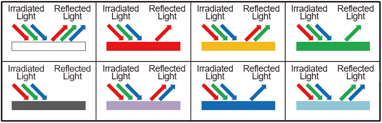
When an object is irradiated with light containing RGB components, the color of the reflected light will change depending on the color of the object.
For example, if the object is red, the reflected light component will be red. For a yellow object, the reflected light will be red and green, and if the object is white all three components will be reflected.

In this way, the color of the object is determined from the ratio of color components (RGB) in the reflected light.
Similarly, the human eye determines color by receiving these reflected light components.
It is impossible to see in the dark. This is because there is no irradiating (illuminating) light, which means there is no reflected light so everything looks pitch black.
Like human eyes, color sensors determine the color by first detecting light (using photodiodes) then calculating the ratio of R, G, and B received.

An overview of the APDS9960 sensor

Gesture detection utilizes four directional photodiodes to sense reflected IR energy (sourced by the integrated LED) to convert physical motion information (i.e. velocity, direc- tion and distance) to a digital information.

Besides that, this sensor has Proximity detection feature which provides distance measurement by photodiode detection of reflected IR energy. It also has color and ALS detection feature  that provides red, green, blue and clear light intensity data. Each of the R, G, B, C channels have a UV and IR blocking filter.

Specification

Application

  • Output type: Digital-I2C
  • Resolution: 16 Bit
  • Peak Wavelength: 950nm
  • Wavelength Range: ~360 to ~1100 nm

For more specifications, please refer to datasheet

  • Gesture Detection
  • Color Sense
  • Ambient Light Sensing
  • Cell Phone Touch Screen Disable
  • Mechanical Switch Replacement

APDS9960 module Key Features

  • On Board, ON/OFF LED indicator
  • I2C interface for reading data and configuring the sensor
  • LED indicator for Dedicated Interrupt Pin
  • Pin Compatible with GEBRABUS
  • It can be used as a daughter board of GEBRABIT MCU Modules
  • Featuring Castellated pad (Assembled as SMD Part)
  • Separatable screw parts to reduce the size of the board
  • Package: GebraBit small (36.29mm x 32.72mm)

GebraBit APDS9960 module

GebraBit APDS-9960 Features advanced Gesture detection, Proximity detection, Digital Ambient Light Sense(ALS), and Color Sense (RGBC) with UV and IR blocking filters.GebraBit APDS-9960 module operates with a “3V3” supply Voltage.

GebraBit APDS-9960 communicates with the I2C protocol and features a LED indicator for Dedicated Interrupt Pin.

Considering that it is difficult to access the sensor pins, the user needs a starter circuit and driver for the hardware development and of course the software development of the APDS-9960 sensor. GebraBit implements the APDS-9960 sensor circuit and provides access for the convenience of users.

It is enough to put the GebraBit APDS-9960 module in the BreadBoard, then by applying the proper voltage set up the GebraBit APDS-9960 module with any of Arduino, Raspberry Pi, Discovery board, and especially we recommend using GebraBit microcontroller development modules (GebraBit STM32F303 or GebraBit ATMEGA32 module) then receive the data.      

The reason for our recommendation when setting up the GebraBit APDS-9960 module with GebraBit microcontroller development modules (such as GebraBit STM32F303 or GebraBit ATMEGA32), is the presence of an internal 3V3 regulator on these modules and the compatibility of the pin order of all GebraBit modules together (GEBRABUS standard), it’s enough to Put the APDS-9960 in the corresponding socket as shown in the above picture and develop the desired sensor module without the need for wiring.     

Introduction of module sections

APDS9960 sensor

APDS-9960 sensor is the Ambient Light sensor of this module which is placed in the center of the module and its circuit is designed.

Interrupt LED

A dedicated LED is considered for the interrupt pin on the module and its status changes when the interrupt state changes according to the sensor data sheet.

Power supply LED

By applying voltage through the “3v3” pin, the module power LED is lit.

GebraBit APDS9960 Module pins

Supply pins

  • 3V3: This pin supply the sensor main power supply and the logic level of the sensor digital connection (I2C).
  • GND: This is the common ground pin for power and logic level of the sensor.

I2C pins

  • SDA: This pin is the I2C communication data pin, which is connected to the corresponding data pin in the microcontroller (processor).
  • SCL: This pin is the I2C communication clock pin, which is connected to the corresponding clock pin in the microcontroller (processor).

Other pins

  • INT : Interrupt pin for APDS-9960 sensor, according to the datasheet , the user can set the interrupt conditions, the modes and methods of the interruption, etc.
  • VLD: This pin is is embedded for APDS-9960’s LED. This LED can be powered by the user separately by applying voltage to the VLD pin, and it can also be powered through the 3V3 pin.

Connect to the processor

I2C connection with GebraBit STM32F303

for i2c communication of GebraBit APDS9960 and GebraBit STM32F303 microcontroller module, after defining SDA and SCL on pins PB9 and PB8 (for convenience in STMCUBEMX), follow the below steps:

  • Connect the 3V3 pin of the APDS9960 module to the 3V3 output pin of the microcontroller module. (red wire)
  • Connect the GND pin of the APDS9960 module to the GND pin of the microcontroller module (black wire).
  • Connect the SCL pin of the APDS9960 module to the PB8 pin of the microcontroller (SCL) module (blue wire).
  • Connect the SDA pin of the APDS9960 module to the PB9 pin of the microcontroller (SDA) module. (yellow wire)

Note: Considering that the PA14 pin of the GebraBit STM32F303 microcontroller module is used to program the microcontroller, I2C setting on the PA14 and PA15 pins is impossible in this version, so in this version for  I2C  connection with the GebraBit STM32F303 microcontroller module, GebraBit APDS9960 module cannot be placed as Pin to Pin on it.

I2C connection with GebraBit ATMEGA32A

Considering that the I2C pins of the ATMEGA32A microcontroller are based on the GEBRABUS standard and correspond to the I2C pins of other GEBRABIT modules, the GebraBit APDS9960  module can be placed pin to pin  on the GebraBit ATMEGA32A module Here, for better understanding, the separate connection of these two modules is shown.

I2C Connection with ARDUINO UNO

follow the below steps to connect the GebraBit APDS9960 module to the ARDUINO UNO:

  • connect the “3V3” pin of the APDS9960 module to the “3V3” output pin of the ARDUINO UNO board. (Red wire)
  •  connect the “GND” pin of the APDS9960 module to the “GND” pin of the ARDUINO UNO board. (Black wire)

  • Connect the SCL pin of the APDS9960 module to the A5 pin of the ARDUINO UNO board (SCL). (blue wire)
  • Connect the SDA pin of the APDS9960 module to the A4 pin of the ARDUINO UNO board (SDA). (orange wire)

How to connect the above mentioned steps, can be seen in this picture:

این مقاله را با دوستانتان به اشتراک بگذارید!

Leave a Reply

Your email address will not be published. Required fields are marked *

Shopping cart
Start typing to see posts you are looking for.

Sign in

No account yet?