GebraBit

GebraBit ADS1191 ECG Module Overview

متن سربرگ خود را وارد کنید

BLOG

GebraBit ADS1191 ECG Module Overview

  1. Home
  2. »
  3. Blog
  4. »
  5. GebraBit ADS1191 ECG Module Overview

Biomedical sensors are special electronic devices that can transduce biomedical signals into easily measurable electric signals. Biomedical sensors are the key component in various medical diagnostic instruments and equipment.

Biomedical sensors have been widely applied in medical image analysis and diagnostics, portable and clinical diagnostics, and laboratory analytical applications.

Biomedical sensors are usually classified according to the quantity to be measured and are typically categorized as physical, electrical, or chemical, depending on their specific applications.

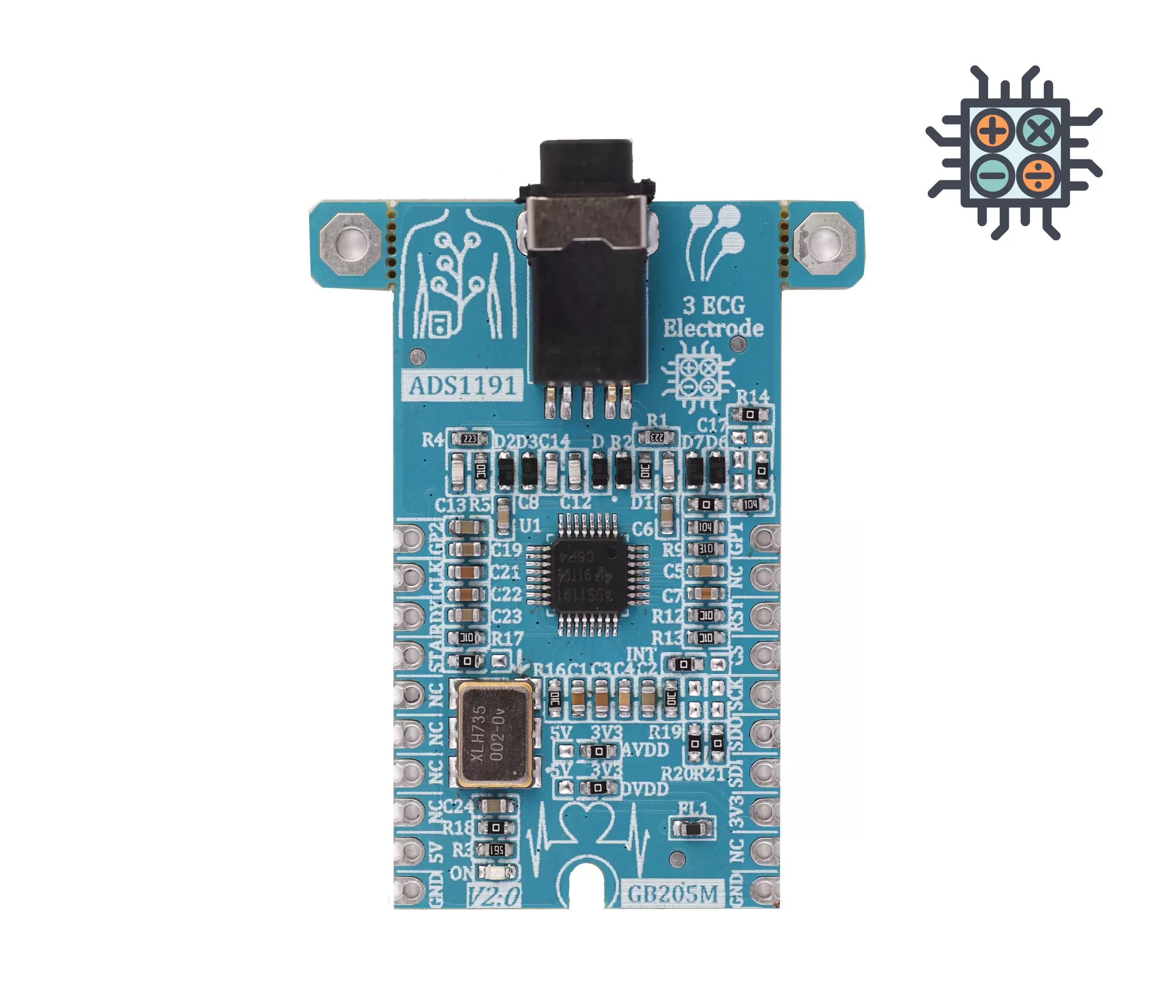
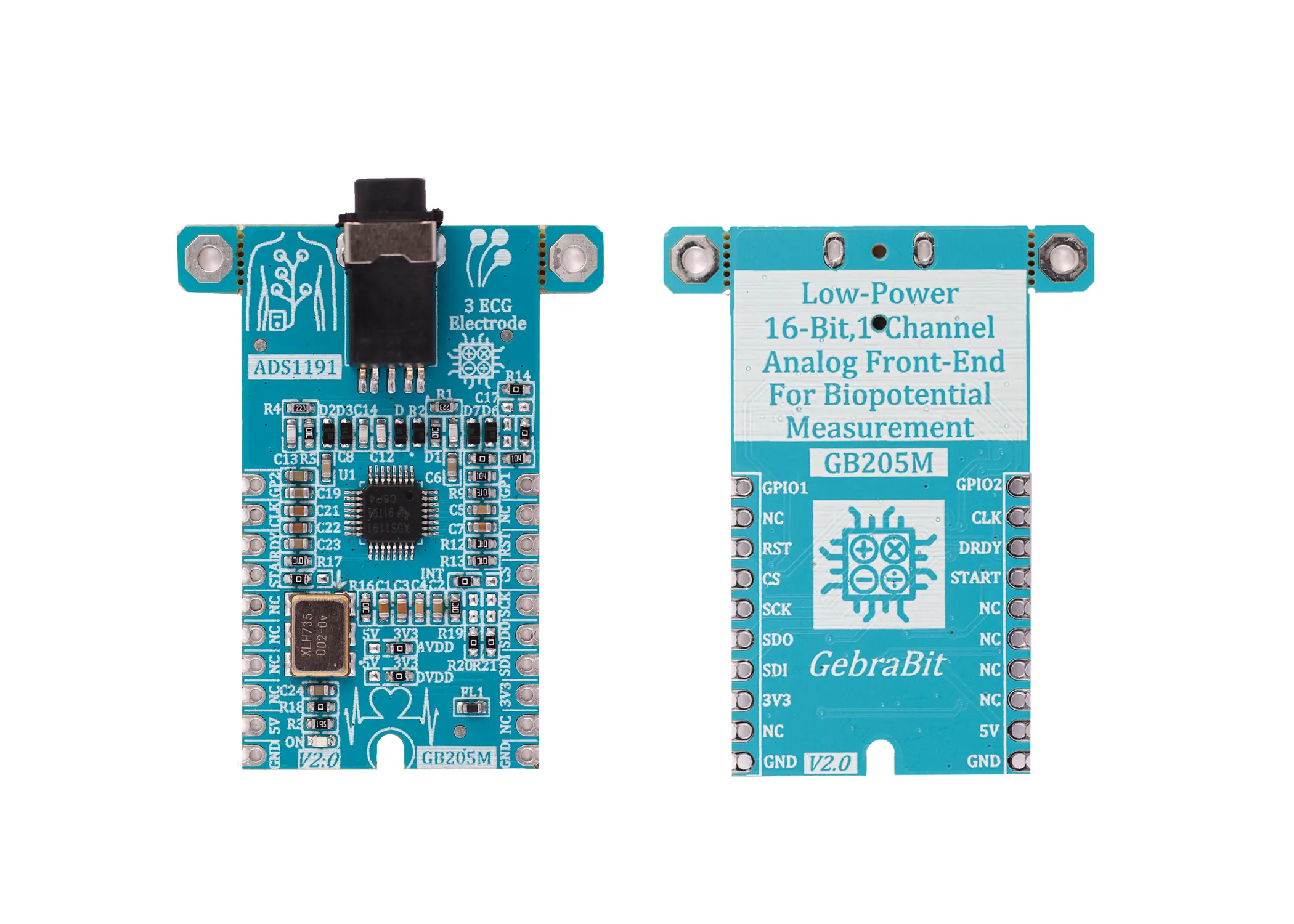
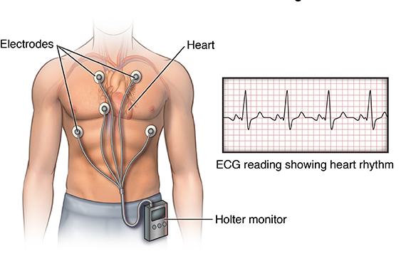
An electrocardiogram records the electrical signals in the heart. It’s a common and painless test used to quickly detect heart problems and monitor the heart’s health.

An electrocardiogram — also called ECG or EKG — is often done in a health care provider’s office, a clinic or a hospital room. ECG machines are standard equipment in operating rooms and ambulances. Some personal devices, such as smartwatches, offer ECG monitoring.

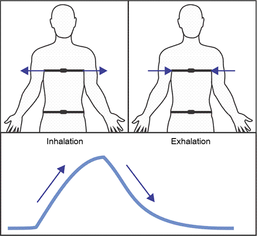
The respiration sensor is a sensitive girth sensor worn using an easy fitting high durability woven elastic band fixed with a length adjustable webbing belt. It detects chest or abdominal expansion/contraction and outputs the respiration waveform.

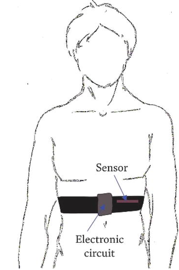
A stretch sensitive device is strapped to the torso to measure the relative amount of expansion that occurs during respiration (breathing). As breathing in takes place the rib cage expands which stretches the device. When exhaling, the stretch relaxes and the sensor returns to its neutral position. The resulting waveform is displayed on the screen.

To monitor thoracic respiration (chest breathing), the strap is positioned to the upper aspect of the trunk. Position it on the lower aspect of the trunk to measure diaphragmatic respiration (stomach breathing).

An overview of the ADS1191 sensor

ADS1191 is a 2 channel 16-bit analog front-end ECG sensor, with simultaneous sampling capability, which is packaged in a 5-mm × 5-mm, 32-pin thin quad flat pack (TQFP). Operating temperature is specified from –40°C to +85°C.

The ADS1191 is a family of multichannel, simultaneous sampling, 16-bit, delta-sigma (ΔΣ) analog-to-digital converters (ADCs) with a built-in programmable gain amplifier (PGA), internal reference, and an onboard oscillator.

This sensor also has a flexible input multiplexer per channel that can be independently connected to the internally-generated signals for test, temperature, and lead-off detection.

Specification

Applications

  • Number Of Channels: 2
  • Output type: Digital – SPI
  • ADC Resolution: 16 Bit
  • Data rate: 125SPSP to 8kSPS

For more specifications, please refer to datasheet

  • Medical Instrumentation (ECG) including:
  • Patient monitoring; Holter, event, stress, and vital signs including ECG, AED, telemedicine
  • Sports and fitness (heart rate, respiration, and ECG)

ADS1191 module Key Features

  • User selectable analog and digital supply voltage
  • User selectable ADS1191 clock source (Internal or external )
  • 2.048 Mhz crystal oscillator
  • Benefits from 1 channel of ADS1191
  • Can use 3-lead ECG cable with 3.5mm phone male jack
  • ON/OFF LED indicator
  • Access to important I/O of ADS1191
  • SPI interface for reading data and configuring the sensor
  • Pin Compatible with GEBRABUS
  • It can be used as a daughter board of GEBRABIT MCU Modules
  • Featuring Castellated pad (Assembled as SMD Part)
  • Separatable screw parts to reduce the size of the board
  • Package: GebraBit medium (36.29mm x 46.18mm)

GebraBit ADS1191 module

GEBRABIT ADS1191

GebraBit ADS1191 is a 3 lead, 1 channel sampling, 16 Bit ECG sensor Module which needs 2 voltages for both analog and digital supply of ADS1191.

GebraBit ADS1191 offers 2 choices for ADS1191 clock source; one is ADS1191 Internal oscillator and the other, external clock source that is provided by an on board “2.048Mhz” crystal oscillator .

Due to considered 3.5mm headphone jack female socket, GebraBit ADS1191 module benefits from 1 channel of ADS1191 sensor. So any 3-lead ECG cable with a 3.5mm phone jack can meet our requirements.

After the above mentioned explanations, you have noticed that according to the TQFP package, the user needs a starter circuit and driver for the hardware development and of course the software development of the ADS1191 sensor. For the convenience of users, this work has been done by implementing the ADS1191 sensor circuit and providing access to the communication and power supply signal pins by GebraBit team.

GEBRABIT ADS1191

It is enough to put the GebraBit ADS1191 module in the BreadBoard, then by applying the proper voltage, connect the GebraBit ADS1191 module with any of the Arduino, Raspberry Pi, Discovery boards, and especially we recommend using GebraBit microcontroller development modules to develop the sensor and receiving data.

The reason for our recommendation when setting up the GebraBit ADS1191 module with GebraBit microcontroller development modules (such as GebraBit STM32F303 or GebraBit ATMEGA32), is the presence of an internal 3V3 regulator on these modules and the compatibility of the pin order of all GebraBit modules together (GEBRABUS standard). It’s enough to put the GebraBit ADS1191 module in the corresponding socket as shown in the above picture and develop the desired sensor module without the need for wiring.

Introduction of module sections

ADS1191 sensor

It’s the main IC of the following module, which is placed in the center of the module and is in charge of heart rate monitoring and respiration.

3.5mm headphone jack

This headphone jack is installed on the module in order to connect the ECG leads to the module and receive heartbeat signals.

Any 3-lead ECG cable with a 3.5mm male phone jack can be used to connect the device to the body. In most three-lead ECG cables, the leads are red, green, and yellow, and the red lead is connected to the right hand, the yellow lead is connected to the left hand, and the green lead is connected to the right leg.

By connecting the male headphone jack of the ECG cable to the corresponding socket on the module and correctly sticking the leads to the body, the module is activated and heart rate monitoring is performed.

The output signal, in terms of shape, cleanliness and voltage level, is similar to the sample signal in the below pic.

internal/external clock source selector jumper

If the 0R resistor is to the left side, the internal clock source, and if the 0R resistor is to the right side, the external clock source is selected.

Note: If the sensor internal/external clock source selector jumper is set to internal and the external clock source selector jumper is on the left side, the internal clock of the sensor will be available on the “CLK” pin.

External clock source selector jumper

If the 0R resistor is on the right side, the on-board embedded “2.048 MHz” crystal oscillator will be activated as an external source, and if the 0R resistor is on the left side, the internal clock source can be received from the “CLK” pin.

2.048MHz Crystal oscillator

According to the state of the external clock source selector jumper and by applying voltage to the module via the corresponding pin, the crystal oscillator of the module will be activated as the external clock source.

Analog supply voltage selector jumper (AVDD)

According to the state of 0R resistance of this jumper, the analog supply voltage of the sensor is selected between 3V3 and 5V.

Digital supply voltage selector jumper (DVDD)

According to the state of 0R resistance of this jumper, the digital supply voltage of the sensor is selected between “3V3” and “5V”.

on/off detection LED

According to the status of “AVDD” and “DVDD” jumpers, by applying voltage to the module via the corresponding pin, this LED will be lit.

GebraBit ADS1191 Module pins

Supply pins

  • 5V and 3V3: These pins can supply the sensor main power according to the state of “AVDD” and “DVDD” selector jumpers.
  • GND: This is the common ground pin for power the module.

SPI pins

  • SDI (MOSI): This pin is used to send data from the microcontroller (processor) to the module (sensor). The abbreviation of this pin is derived from the Latin phrase Serial Data In / Microcontroller Out Sensor In.
  • SDO (MISO): This pin is used to send data from the module (sensor) to the microcontroller (processor). The abbreviation of this pin is derived from the Latin phrase Serial Data Out / Microcontroller In Sensor Out.
  • SCK: This pin is the clock pin for SPI communication, which is considered as an input for the sensor and is connected to the corresponding clock pin in the microcontroller (processor).
  • CS: This pin is the Chip Select pin for SPI communication with the module (sensor), which is selected by applying LOW voltage (0V), the module (sensor) for SPI communication. This pin is input type for the sensor.

If you want to use several GebraBit ADS1191 modules at the same time, it is enough to connect the “SDO”, “SDI”, “SCK” pins of all modules and the microcontroller (processor) and assign a unique pin to each “CS”.

input/output pins

  • GP1: This pin is the GPIO1 pin of the module, which can be used as a general-purpose input/output pin.
  • GP2: This pin is the GPIO2 pin of the module, which can be used as a general-purpose input/output pin.

Other pins

  • RST: This pin is an active low pin and used to reset the system.
  • RDY: This pin is the digital output pin of the module, which is set to active-low when the data is ready.
  • STA: This pin is the start pin of the module and it is intended to start the conversion.

Connect to the processor

SPI connection with GebraBit STM32F303

To connect the GebraBit ADS1191 module to the GebraBit STM32F303 microcontroller module via SPI protocol, after defining “SDI”, “SDO”, “SCK”, and “CS” on PB5, PB4, PB3, and PC13 pins (for convenience in STMCUBEMX), place the GebraBit ADS1191 module Pin to Pin on the GebraBit STM32F303 module easily.Here for better understanding the separate connection of these two modules is shown.

SPI connection with GebraBit ATMEGA32A

Considering that the SPI pins of the ATMEGA32A microcontroller are based on the GEBRABUS standard correspond to the SPI pins of other GEBRABIT modules, the GebraBit ADS1191 module can be placed pin to pin on the GebraBit ATMEGA32A module and communicate with the GebraBit ATMEGA32A module via SPI.Here for better understanding the separate connection of these two modules is shown.

NOTE: If you are using GebraBit microcontroller modules, note that the power selector jumpers of the GebraBit ADS1191  are set to “3V3” so that you can easily power-on the GebraBit ADS1191 module by getting the “3V3” voltage from the microcontroller module.

SPI Connection with ARDUINO UNO

Follow the below steps to connect module GebraBit ADS1191 to ARDUINO UNO via SPI protocol:

  • Connect the “3V3” pin of ADS1191 module to the “3V3” output pin of the ARDUINO UNO board. (red wire)

Connect the “GND” pin of the ADS1191 module to the “GND” pin of the ARDUINO UNO board (black wire).

  • Connect the “SDI” pin of the ADS1191 module to the D11 pin of the ARDUINO UNO board (SDI). (yellow wire)
  • Connect the “SDO” pin of the ADS1191 module to the D12 pin of the ARDUINO UNO board (SDO). (Purple wire)
  • Connect “SCK” pin of ADS1191 module to D13 pin of ARDUINO UNO board (SCK). (Orange wire)
  • Connect the “CS” pin of the ADS1191 module to the D10 pin of the ARDUINO UNO board (CS). (blue wire)

You can see how to connect the above mentioned steps in this picture:

این مقاله را با دوستانتان به اشتراک بگذارید!

Leave a Reply

Your email address will not be published. Required fields are marked *

Shopping cart
Start typing to see posts you are looking for.

Sign in

No account yet?