What's the purpose of this project?
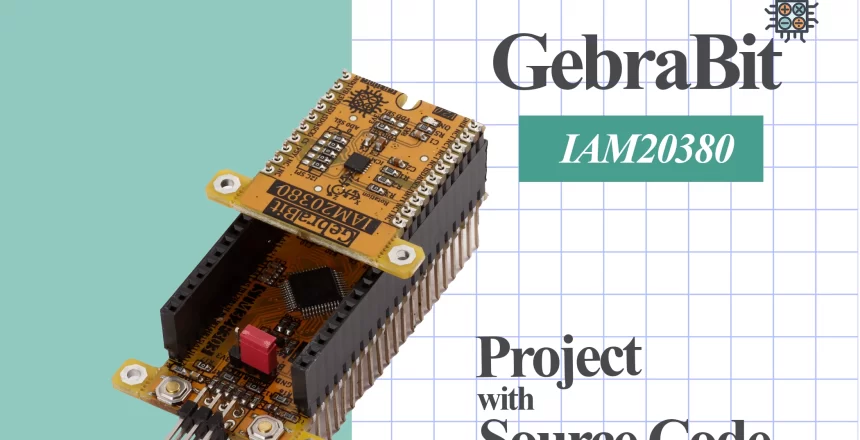
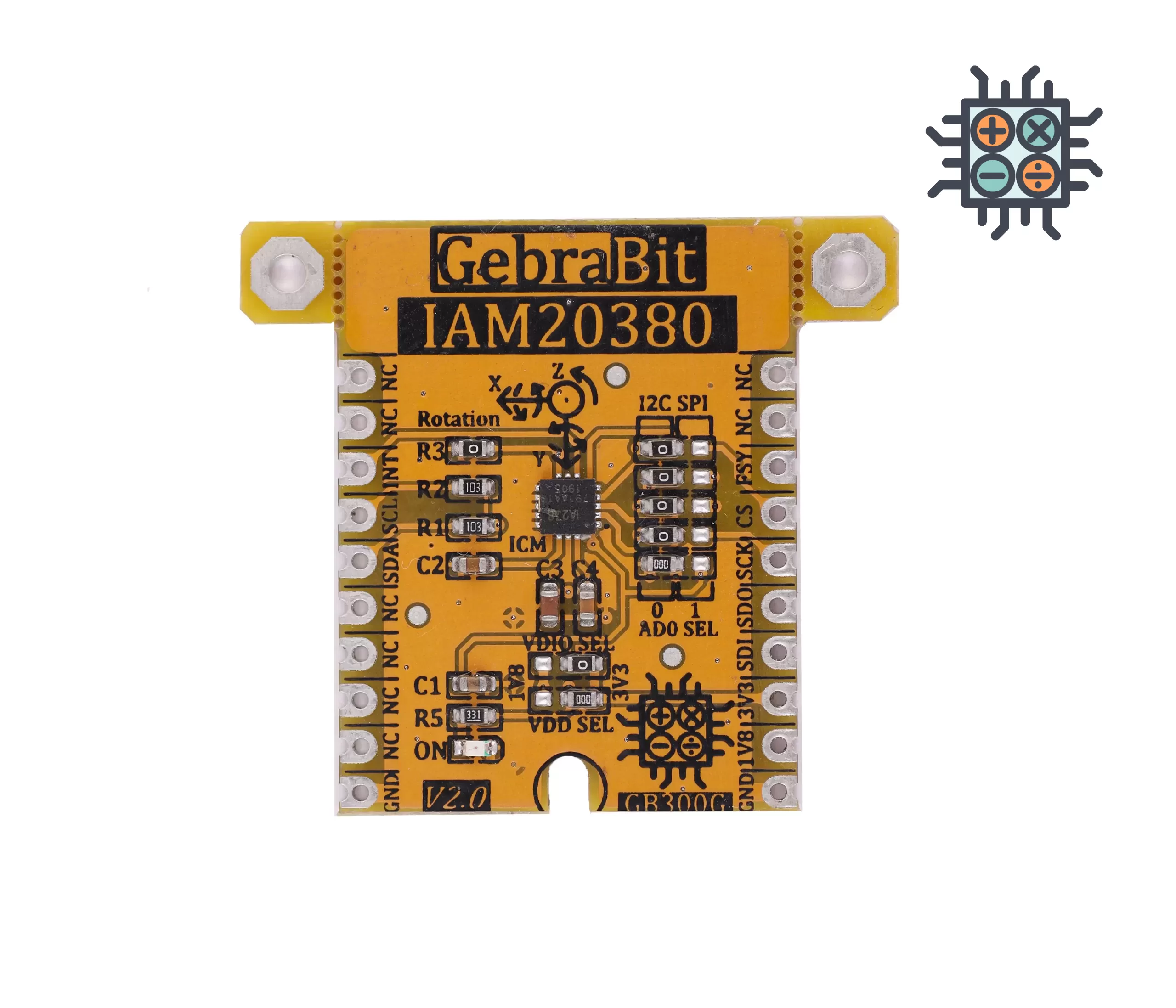
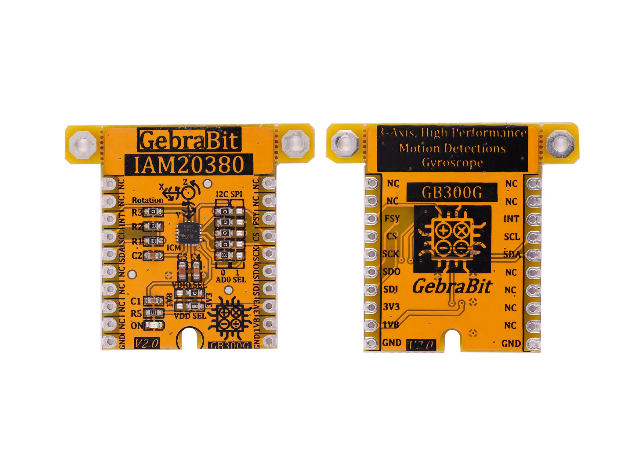
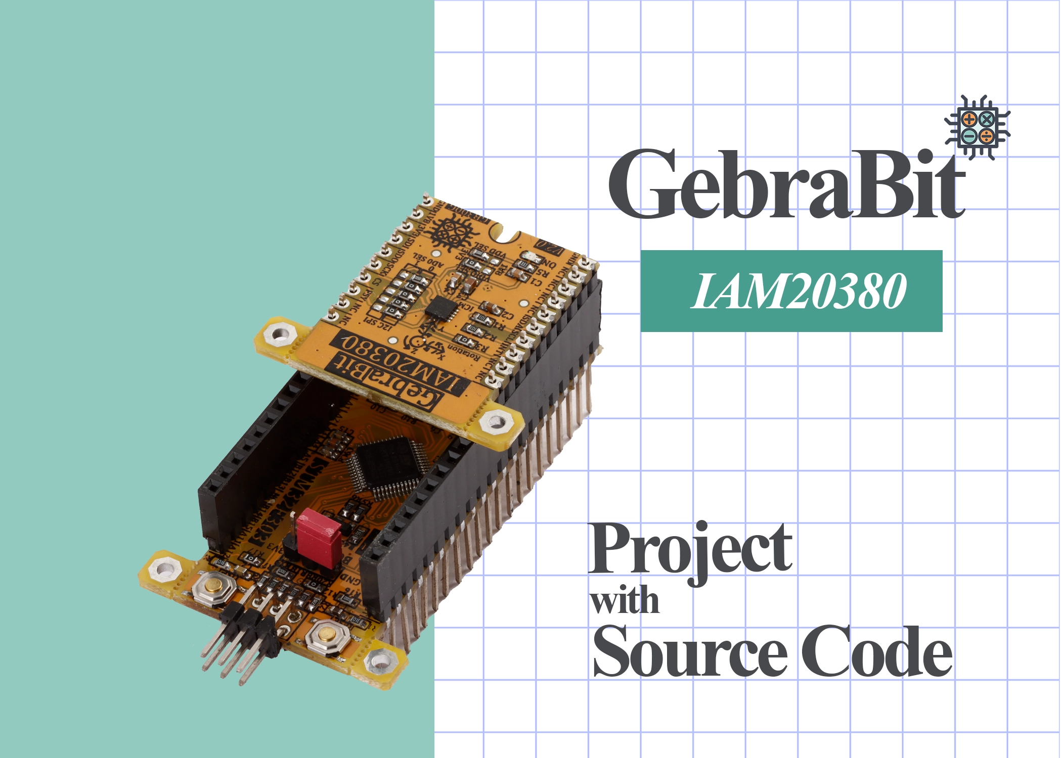
In this section, we are going to launch the IAM20380 sensor using ARM microcontroller, STM32F series. In order to use more conveniently and optimally in this project, we use two ready modules GB300G and GebraBit STM32F303. These two modules contain the minimum necessary elements of the IAM20380 sensor and the STM32F microcontroller, which are provided by the GebraBit team to facilitate the work.
What are we going to learn in this tutorial?
In this tutorial, in addition to setting up and using the IAM20380 sensor, you will get to know all the IAM20380 sensor registers, how to set the various parts of the STM32 microcontroller to set up this sensor using the I2C protocol, how to use the GB300G module specific library and driver file. You will also learn how to declare functions and finally receive sensor data in the Keil compiler.
What do we need to start this project?
As you probably know, we need some hardware and software to do this project. The titles of these hardware and software are provided to you in the table below and you can prepare/download by clicking on each of them and get ready to start.
|
Required hardware
|
Required software
|
|---|---|
|
Keil compiler
|
|
|
STM32CubeMX program
|
|
|
ST-LINK/V2 programmer
|
IAM20380 STM32CubeMX settings
In the following, we review the settings related to each of the “I2C”, “RCC”, “Debug”, and “Clock” sections in the STM32F303 microcontroller to develop the GebraBit IAM20380 module.
RCC settings
Due to the presence of “8Mhz” crystal in the GebraBit STM32F303 module, we select the “external clock” in the “RCC” section:

Debug & Programming settings
Regarding the access to “SWCLK” and “SWDIO” pins in the GebraBit STM32F303 module, to reduce the number of pins during “Debug & Programming”, in the “SYS” block, we select the “Serial Wire” option in the “Debug” section:

I2C settings
To communicate via I2C with the GebraBit STM32F303 module, we choose “PB8” and “PB9” pins as SCL and SDA to avoid interfering with the “Serial Wire” mode, during “Debug&Programming”:

Clock settings
The “clock” settings for each part of the STM32F303 microcontroller in this code, are as follows:

Project Manager settings
“Project Manager” settings are as follows, here we have used “MDK-ARM” version “5.32” compiler:

After completing all the above settings, we can develop our code easily just by one click on “GENERATE CODE” and adding the IAM20380 library and driver (provided by GebraBit).
You can download the “STM32Cube MX”, “IAM20380 library”, “driver” and KEIL project in the end of this tutorial.
IAM 20380 library and driver

In addition to the modular design of various sensors and ICs, GebraBit tries to provide variety of structured and hardware-independent libraries in C language for the ease of users in setting up and developing software.
For this purpose, after preparing each GebraBit module, the users can refer to the “training” section of the desired module and download the dedicated library, which contains the “ .h” and “ .c” file (Header and Source) and a sample training program under “GebraBit STM32F303”, “GebraBit ATMEGA32A” or “Arduino” development boards.
All the defined functions and structures in the library are commented in full detail and all the received parameters in the arguments of the functions and their return values, are briefly explained. Since the libraries are hardware independed. , the user can easily add the library in any of their favorite compilers and develop it by desired microcontroller and development board.
IAM20380.h header file
In this file, based on the datasheet of the sensor or IC, all the registers addresses, the registers values and the structures of different registers settings, for a specific configuration are defined.
Gyro_Data structure
All information that can be received from a GebraBit IAM20380 module is defined in this structure:

IAM_20380_Conf structure
The main settings of the GebraBit IAM20380 module, which are related to registers “26” and “27”, are defined in this structure:

IAM_20380_FIFO_CFG structure
The FIFO settings of the GebraBit IAM20380 module, which includes registers “26”, “35”, “56”, and “106”, are defined in this structure:

IAM_20380_LP structure
“LOW POWER” mode settings of GebraBit IAM20380 module, which includes registers “25” and “30”, are defined in this structure:

IAM_20380_INT_CFG structure
All interrupt settings of the GebraBit IAM20380 module, such as “interrupt type”, “occurrence time”, “logic level”, etc., which includes registers “55” and “56”, are defined in this structure:

IAM_20380_INT_STATUS structure
The status of the generated interrupt in the GebraBit IAM20380 module, which can be checked by reading registers “54” and “58”, is defined in this structure:

IAM_20380_PWR structure
All “POWER MANAGEMENT” settings of GebraBit IAM20380 module, which includes registers “107” and “108”, are defined in this structure:

IAM_20380_SET structure
Finally, IAM_20380_SET is the general structure of the GebraBit IAM20380 module, which is defined using the above mentioned structures. In fact, the user only initializes this structure for the GebraBit IAM20380 module settings, and then initializes all the values for the GebraBit IAM20380 module by using the “IAM_20380_init()” function.

IAM20380.c Source file
In this file, which is written in C language, all the functions are commented in full detail and all the parameters received in the arguments of the functions and their return values are completely explained as in the below picture. So, in this section We are satisfied with these explanations and invite users to check this file directly for more information.


Sample program in Keil
After making the Keil project by STM32CubeMX and adding the IAM20380 library provided by GebraBit, we will examine the “main .c” file of the sample tutorial and view the output of the GebraBit IAM20380 module in the “watch” part in the the Keil compiler “Debugging” environment.
Description of “main.c” file
If you look carefully at the beginning part of the “main.c” file, you will notice that the “IAM_20380.h” header has been added to access the structures and functions required by the GebraBit IAM20380 module. In the next part, there are variables such as “FIFO_Buffer[515]” to store the IAM20380 buffer data and a variable that is defined as “Setting_Struct” which is derived from IAM_20380_ structure (this structure is in IAM_20380.h header and explained in IAM20380 library description section) which is for GebraBit IAM2038 configuration.

In the next part of the written code, the configuration and settings of the GebraBit IAM20380 module are done by using the Setting_Struct variable . finally, the GebraBit IAM20380 module is initialized by referencing the “Setting_Struct” structure to the argument of the “IAM_20380_init() “ function.

at last, in the “while” part of the program, the acceleration values of GebraBit IAM20380 module are received continuously in 3 axes (X, Y, Z):

In the context of the written program in “main.c”, there are other functions that are used as comments. You can benefit from these functions by uncommenting each of them.
Program output
Now we connect STLINK V2 programmer to GebraBit STM32F303 using STLINKV2 adapter:

By connecting the STLINK V2 programmer to the GebraBit STM32F303, there is no need to apply power to the GebraBit STM32F303 and GebraBit IAM20380 modules, because they receive their supply voltage directly from the STLINK V2 programmer.
Finally, enter the “Debug” mode and by adding the “Gyro_Data_Value” variable (which is derived from the Gyro_Data structure and is defined in the “IAM20380.C” file) to the “watch” window and running the program, we can see the changes in the GebraBit IAM20380 module values in the 3 axes( X, Y, Z)”

In the following, you can download this project in the Keil environment and also the “STM32CubeMX file” and “ modules schematic” and the “IAM 20380 datasheet”.
