GebraBit

GebraBit Conductivity Sensor Module Overview

متن سربرگ خود را وارد کنید

conductivity both sides

GebraBit Conductivity Sensor Module Overview

  1. Home
  2. »
  3. Blog
  4. »
  5. GebraBit Conductivity Sensor Module Overview

Conductivity is the ability of a substance to carry the current. It is the reciprocal of resistivity. In liquid, we often use the reciprocal of resistance, and conductance, to measure the conductive capacity.

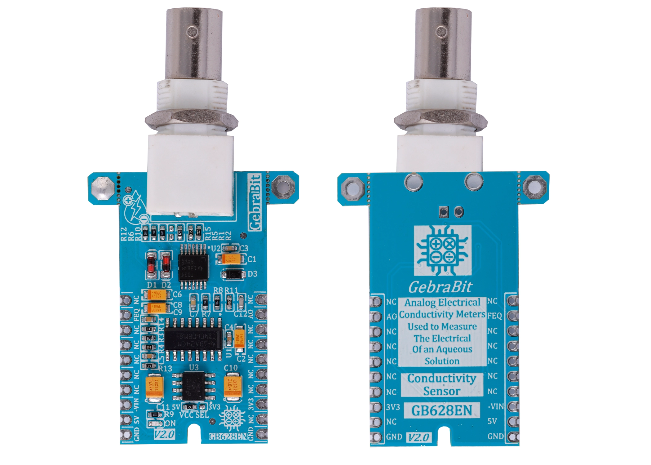
A conductivity sensor measures the ability of a solution to conduct an electrical current. It is the presence of ions in a solution that allow the solution to be conductive: the greater the concentration of ions, the greater the conductivity.

A conductivity meter emits an electrical charge via a conductivity probe, which is dipped into the solution being tested. If there is an increase or decrease in the number of dissolved ions, it will result in an increase or decrease in the electrical charge. A conductivity meter can measure this charge, and provide you with the solution’s conductance.

When the probe is inserted into the solution, electrical current flows between the two electrons inside the probe, set apart at a specific distance. The ion concentration in the solution is what determines if the conductance is high or low. If the ion concentration is high, the higher the conductance will be, which results in a faster current. If the electrical current is slow, the conductance value will be lower because the concentration of ions in the solution is less.

GebraBit Conductivity sensor module

GEBRABIT Conductivity module is an electrical conductivity meter (EC meter) that measures the electrical conductivity in a solution. GEBRABIT Conductivity is capable of using 3V3 and 5V Supply Voltages that users can easily select with considered onboard jumper select. This feature helps to use a wide range of microcontrollers for interfacing with this module.

The method of measuring the conductivity of water in this module is to measure the amount of current based on the voltage applied to the probe plates placed in the water.

To access the output data, it is enough to put the GebraBit Conductivity Sensor module in the BreadBoard, then by applying the proper voltage set up the GebraBit Conductivity Sensor module with any of Arduino, Raspberry Pi, Discovery board, and especially we recommend using GebraBit microcontroller development modules (GebraBit STM32F303 or GebraBit ATMEGA32 module) then receive the data. 

The reason for our recommendation when setting up the GebraBit Conductivity Sensor module with GebraBit microcontroller development modules (such as GebraBit STM32F303 or GebraBit ATMEGA32), is the presence of a 3V3 regulator and the compatibility of the pin order of all GebraBit modules together (GEBRABUS standard), it’s enough to Put the GebraBit Conductivity Sensor module in the corresponding socket and develop the desired sensor module without the need for wiring.    

GebraBit Conductivity sensor module Key Features

  • User-selectable module power supply voltage between 3V3 and 5V
  • On Board, ON/OFF LED indicator
  • GEBRABIT Pin Compatible with GEBRABUS
  • GEBRABIT small package
  • It can be used as a daughter board of GEBRABIT MCU Modules
  • Featuring Castellated pad (Assembled as SMD Part)
  • Separatable screw parts to reduce the size of the board

Introduction of module sections

BNC connector

A BNC connector is used to connect the sensor probe to the module, which is placed on top of the module.

CD4060 IC

This IC is responsible for generating the AC signal for the probe first plate.

TL034 op amp

In the GebraBit Conductivity Sensor circuit, a TL034 op-amp is used as a buffer and to isolate the CD4060 output.

LM2660 convertor

In the GebraBit Conductivity Sensor module, a LM2660 convertor is used to produce the negative power supply of op-amps.

VCC SEL

According to the state of 0R resistance of this jumper, the sensor supply voltage is selected between 5V and 3V3.

Power LED

According to the status of the module power selector jumper and by applying voltage to the module through the corresponding pin, the LED of the module turns on.

GebraBit Conductivity sensor Module pins

Supply pins

  • 3V3 and 5V: These pins can supply the power supply of the sensor circuit according to the state of the power voltage selector jumper.
  • GND: This is the ground pin for powering the sensor.

Output pin

  • AO: This pin is used to receive the analog output of the module and outputs the conductivity as an analog voltage.

Other pins

  • FEQ: The generated frequency is provided to the user through this pin.

Connect to the processor

Connection with GebraBit STM32F303

Due to the compatibility of the pin order of GebraBit modules with each other (GEBRABUS standard), to start the GebraBit Conductivity sensor module with GebraBit STM32F303 microcontroller module, it is enough to easily place the GebraBit Conductivity sensor module as pin to pin on the GebraBit STM32F303 module and start the module by applying voltage. Here, for better understanding, the separate connection of these two modules is shown:

Connection with GebraBit ATMEGA32A

Due to the compatibility of the pin order of GebraBit modules with each other (GEBRABUS standard), to start the GebraBit Conductivity sensor module with the GebraBit ATMEGA32A microcontroller module, it is enough to easily place the GebraBit Conductivity sensor module as pin to pin on the GebraBit ATMEGA32A module and start the module by applying voltage. Here, for better understanding, the separate connection of these two modules is shown:

Note: If you use GebraBit microcontroller modules, make sure that the VCC SEL selector jumper of GebraBit Conductivity sensor module is set to “3V3” so that you can easily get “3V3” voltage from the microcontroller module.

Connection with ARDUINO UNO

Follow the steps below to connect the GebraBit Conductivity sensor module to ARDUINO UNO:

  • Connect the “5V” pin of the Conductivity sensor module to the “5V” pin of the ARDUINO UNO board output (red wire).
  • Connect the “GND” pin of the Conductivity sensor module to the “GND” pin of the ARDUINO UNO board. (Black wire)
  • Connect the “AO” pin of the Conductivity sensor module to one of the ARDUINO UNO board analog pins (orange wire).

How to connect the above mentioned steps can be seen in this picture:

این مقاله را با دوستانتان به اشتراک بگذارید!

Leave a Reply

Your email address will not be published. Required fields are marked *

Shopping cart
Start typing to see posts you are looking for.

Sign in

No account yet?