In robotics, there are many types of motors such as DC motors, servo motors, stepper motors, etc. Choosing the right motor for a robotics project depends on the user’s intended application and there are different ways to use them.
Some motors can directly be controlled and run in a variety of ways, such as connecting a power supply directly to them. But if we want to control these motors using other control devices like wireless systems, microcontrollers, etc., we need something known as “MOTOR DRIVERS”.
Motor drivers act as interfaces between motors and control circuits. The motor requires high current while the controller circuit operates on low current signals. Therefore, the function of motor drivers is to take a low current control signal and convert it into a higher current signal that can drive the motor.

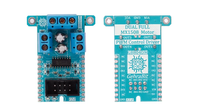
GebraBit MX1508 module

Gebrabit MX1508 is a 4A, up to 35V dual channel motor driver module and needs two separate power supplies for the internal circuitry and motors.
Users can connect motors to the GebraBit MX1508 with voltages between 2 to 9V with a peak current up to 1.5A.
Users can access the most important pins of the MX1508 through the GebraBit MX1508 module. Pins like “IN1”, “IN2”, “IN3″, “IN4” as direction control pins. For easy accessibility, GebraBit MX1508 gives access to the “VCC”, “GND”, and “IN1”, “IN2”, “IN3”, “IN4” pins by a 2×4 pin IDC connector to extend them on other boards.

To use this module it is enough to put the GebraBit MX1508 module in the BreadBoard, then by applying the proper voltage, set-up the GebraBit MX1508 module. Because of the compatibility of the GebraBit MX1508 module pins with the GebraBit STM32F303 pins, we recommend using the GebraBit STM32F303 microcontroller development module for testing and setting up this module.To do so, you just need to put the GebraBit MX1508 module as Pin-to-Pin on the GebraBit STM32F303 module.

GebraBit MX1508 module Key Features
- On Board, ON/OFF LED indicator for “VCC” and “VM”
- On Board LED indicator for direction pins
- Control Pin access with IDC connector
- Screw terminal blocks for power and motor connections
- GebraBit Pin Compatible with GEBRABUS
- It can be used as a daughter board of GebraBit MCU Modules
- Featuring Castellated pad (Assembled as SMD Part)
- Separatable screw parts to reduce the size of the board
- Package: GebraBit medium (36.29mm x 46.18mm)
- Schematic (.pdf)
Introduction of module sections

MX1508 motor driver
It’s the main IC of the following module, which is in charge of controlling the motors and is placed in the center of the module.

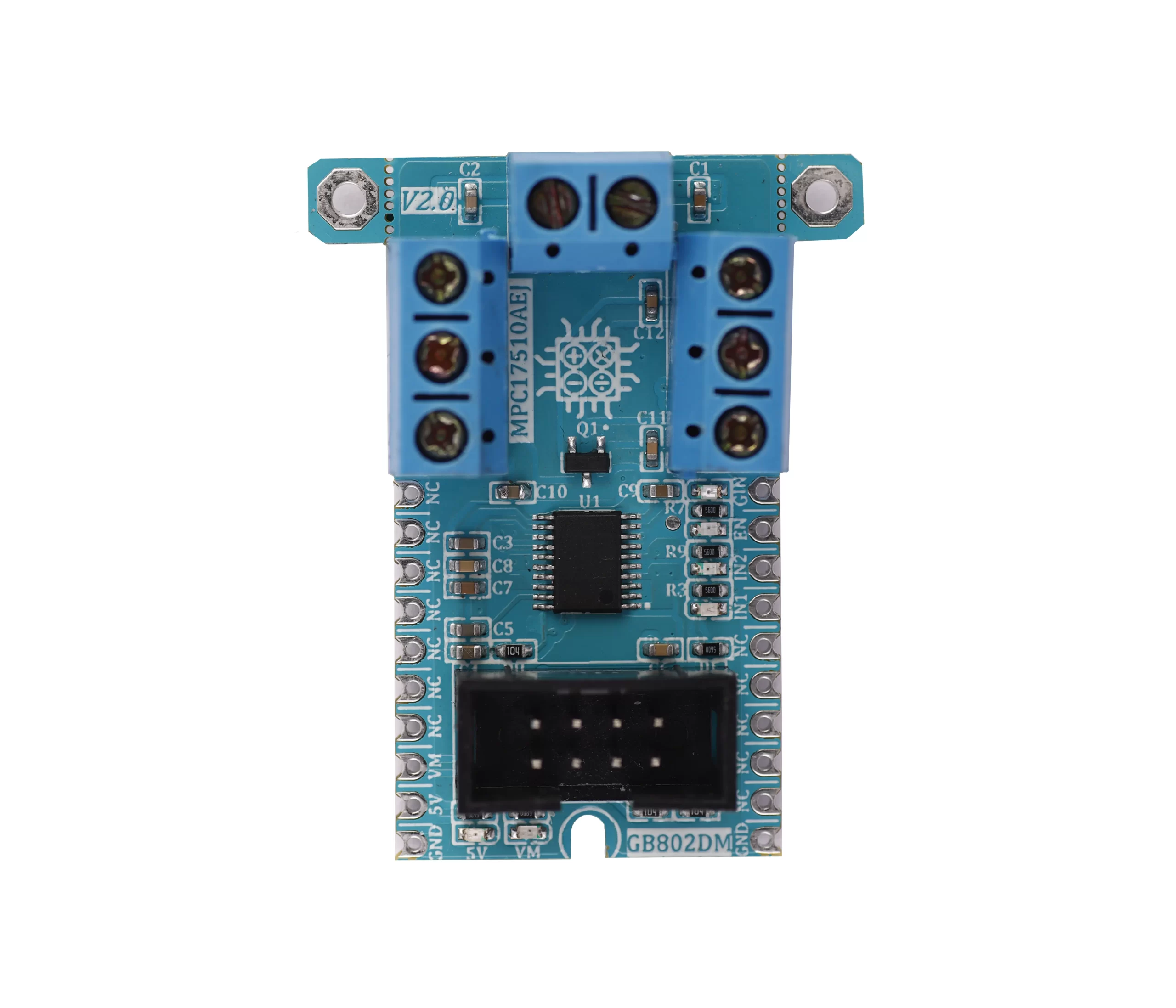
Motor terminal block
GebraBit MX1508 has two screw terminal blocks for “OUT1” to “OUT4” to connect motors.
As you can see in the below pic, the left terminal block is installed for”OUT1” and “OUT2” and the right one is for “OUT3” and “OUT4”.

power supply terminal block
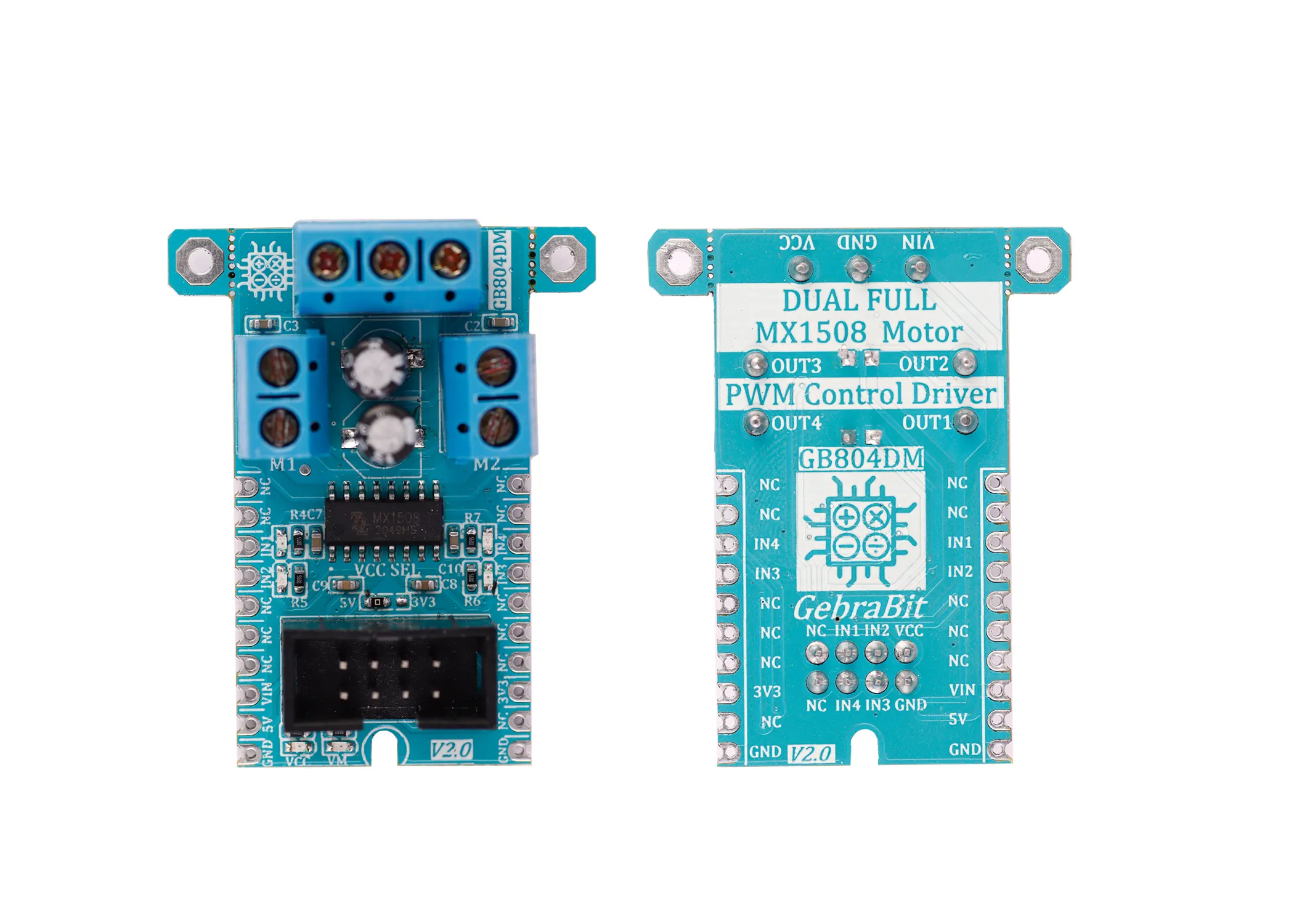
The third terminal block on this module is the power supply terminal which is considered to connect “VCC”, “GND” and “VIN” to the module.

IN pins LEDs
Each of the “IN1”, “IN2”, “IN3”, “IN4” pins of the module, which are intended to control the movement direction of the motors, have a dedicated LED, which will be lit by applying voltage to each of these pins.

signal port
For easier access to the “VCC”, “IN1”, “IN2″,” IN3″, “IN4” and “GND” pins, an ” IDC-2×4″ connector is installed on the GebraBit MX1508 module, which helps the users to connected to the mentioned pins easier just by connecting an appropriate IDC cable to this connector.
You can see how the pins are arranged in the below picture.

VCC selector jumper
As it was said, GebraBit MX1508 needs two separate power supplies for the internal circuitry and motors.
The internal circuitry can operate with “3V3” or “5V” supply Voltages by Considered “VCC SEL” selector jumper or “VCC” pin of the screw terminal block.
According to the state of the “VCC SEL” jumper 0R resistance, the supply voltage of the IC is determined between “5V” or “3V3”.

Power LEDs
VCC LED: According to the state of the “VCC SEL” jumper 0R resistance and by applying a proper voltage to the module through the corresponding pin, the VCC LED of the module will be lit.

VM: By applying voltage to the “VIN” pin, this LED will turn on.

GebraBit MX1508 Module pins

Supply pins
- VIN: The “VIN” pin provides the required voltage to start the motor.
- 5V and 3V3: If the “VCC” selector jumper is set to “5V”, the “5V” pin is responsible for supplying the IC required voltage, and if the “VCC” selector jumper is set to “3V3”, the “3V3” pin does this.
- GND: This is the common ground pin for power and logic level of the sensor.

Direction Control pins
- IN1,IN2,IN3 and IN4: “IN1”and “IN2” are the direction control pins for motor A and the “IN3” and “IN4” are the direction control pins for motor B.

Note: To control each motors speed, it is enough to apply PWM signal to each of the IN1 /IN2 and IN3/IN4 inputs of the motors.

Connect to the processor

connect to GebraBit STM32F303
To connect the GebraBit MX1508 module to the GebraBit STM32F303 microcontroller module, due to the compatibility of the pins of this module with the GebraBit STM32F303 pins, it is enough to place it on the microcontroller as Pin to Pin then you can start the motor just by applying “5V” voltage to the “5V” pins of GebraBit MX1508 and GebraBit STM32F303 modules and a proper voltage to the “VIN” pin.
Here for better understanding the separate connection of these two modules is shown.

Due to the existence of the “3V3” regulator on the GebraBit STM32F303 microcontroller module, even if the “VCC SEL” jumper of the GebraBit MX1508 module is set to “3V3”, you can easily put the GebraBit MX1508 module as Pin to Pin on the GebraBit STM32F303 microcontroller and enable the module by applying voltage.
connect to GebraBit ATMEGA32A
To connect the GebraBit MX1508 module to the GebraBit ATMEGA32A microcontroller module, after connecting a 5V power supply to GebraBit ATMEGA32A power pins and connecting the “GND” and “5V” pins of the two modules to each other, it is enough to connect each of the “IN1” or “IN2” and “IN3” or “IN4” pins of the GebraBit MX1508 module to one of the GebraBit ATMEGA32A PWM pins (OC1A and OC1B pins) and then Connect the remaining pins of MX1508 to the other pins of the microcontroller.

Due to the existence of the “3V3” regulator on the GebraBit ATMEGA32A microcontroller module, if the “VCC SEL” jumper of the GebraBit MX1508 module is set to 3V3, you can easily connect the GebraBit MX1508 module to the GebraBit ATMEGA32A microcontroller in the same way but You should note that in this case instead of Connecting the “5V” pins of this two modules together, you need to connect their “3V3” pins.
Attention: We applied 9V voltage to the modules assuming that the “9V” voltage does not harm the motors.
connect to ARDUINO UNO
follow the below steps to connect the GebraBit MX1508 module to the ARDUINO UNO:
- Since the “VCC SEL” jumper is set on “5V”, Connect the “5V” pin of MX1508 module to the “5V” output pin of the ARDUINO UNO board. (red wire)
- Connect the “GND” pin of the MX1508 module to the “GND” pin of the ARDUINO UNO board (black wire).
- Connect the “VIN” pin of the MX1508 module to the “VIN” pin of the ARDUINO UNO board.(orange wire)
- For each of the motors, connect one of the “IN1” or “IN2” and “IN3” or “IN4” pins of the MX1508 module to one of the ARDUINO UNO PWM pins and connect the other pins of the MX1508 module to the Arduino UNO other pins.
You can see how to connect the two modules according to the above mentioned Descriptions, in the below picture:

Note: when you use the Arduino board to start the MX1508 module, if your Arduino board is connected to the computer and gets its power from the USB port of the computer, you should note that the computer USB port does not flow more than 500mA. So it is better to use a better voltage source for Arduino.
Note 2: When applying voltage to the VIN pin, pay attention that the applied voltage is not higher than the maximum working voltage of the motors you have, otherwise the motors will be damaged.


