The resistance temperature detector (RTD), is a thin film device made of platinum, which is used for measuring temperature. It has great stability, accuracy and repeatability. An RTD is a passive device. It does not produce an output on its own. External electronic devices are used to measure the resistance of the sensor by passing a small electrical current through the sensor to generate a voltage.
An overview of the MAX31865 convertor

The MAX31865 is an easy-to-use resistance-to-digital converter optimized for platinum resistance temperature detectors (RTDs). An external resistor sets the sensitivity for the RTD being used and a precision delta-sigma ADC converts the ratio of the RTD resistance to the reference resistance into digital form. The MAX31865’s inputs are protected against overvoltage faults as large as ±45V.
Specification
Application
- Output Type: Digital-SPI
- Temperature range: -200°C to +800°C
- Temperature Accuracy: ± 0.5°C
For more specifications, please refer to datasheet
- Industrial Equipment
- Medical Equipment
- Instrumentation
MAX31865 module Key Features
- User selectable RTDs 2, 3 or 4 wire topology via input connector and on board jumper select
- On Board, ON/OFF LED indicator
- On Board, DRDY LED indicator
- Pin Compatible with GebraBus
- It can be used as a daughter board of GebraBit MCU Modules
- Featuring Castellated pad (Assembled as SMD Part)
- Separatable screw parts to reduce the size of the board
- Package: GebraBit small (36.29mm x 32.72mm)
GebraBit MAX31865 module

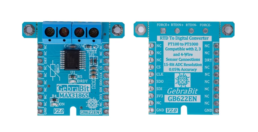
GebraBit MAX31865 is a sophisticated RTD to digital converter with a built in 15 bit analog to digital converter (ADC) and SPI communication interface which operates with “3V3” supply Voltage. GebraBit MAX31865 is optimized to work with PT100 through PT1000 platinum resistance temperatures (RTDs) or thermistors with 2, 3 or 4 wire topology. Users can easily select the RTDs wire topology with on board jumper selector and connections of RTD wires through screw terminal block. Fault detections Such as Open RTD Element, RTD Shorted to Out of Range Voltage, or Short across RTD Element is the other features of this module.
User needs a starter circuit and driver for the hardware development and of course the software development of the MAX31865 converter. For the convenience of users, this work has been done by implementing the MAX31865 converter circuit and providing access to the communication and power supply signal pins.

It is enough to put the GebraBit MAX31865 module in the BreadBoard, then by applying the proper voltage, set up the GebraBit MAX31865 module with any of Arduino, Raspberry Pi, Discovery board, and especially we recommend using GebraBit microcontroller development modules( GebraBit STM32F303 or GebraBit ATMEGA32 module) then receiving the data.

The reason for our recommendation when setting up the GebraBit MAX31865 module with GebraBit microcontroller development modules (such as GebraBit STM32F303 or GebraBit ATMEGA32), is the presence of an internal 3V3 regulator on these modules and the compatibility of the pin order of all GebraBit modules together (GEBRABUS standard), it’s enough to Put the MAX31865 in the corresponding socket as shown in the above picture and develop the desired sensor module without the need for wiring.
Introduction of module sections

MAX31865 converter
MAX31865 is the main IC of the following module which is responsible for converting RTD data to digital data. It is located in the center of the module and its circuit is designed.

RTD wires connection terminal block
A terminal block is provided on the module to connect the wires to the module. The arrangement of the terminal block pins is shown in the figure below.

Terminal block pins introduction:
- RTD IN+: It’s the RTD positive input pin.
- RTD IN-: It’s the RTD negative input pin.
- FORCE+: This pin is the RTD drive high-side pin and when you need two wires connection, it should be connected to RTD+ using a jumper wire.
- FORCE-: This pin is the RTD return low-side pin and when you need two wires connection or three wires connection, it should be connected to RTD+ using a jumper wire.
Note: Don’t connect anything for four wires connection.
RTD wire topology selector jumper
In the GebraBit MAX31865 module, it is possible for users to choose the wire topology by the Wire SEL jumper. If the 0R resistance of this selector jumper is on the left side, 2 and 4 wire topologies are selected, and if the 0R resistance is on the right side, the 3 wire topology is selected.

DRDY LED
In this module, a dedicated LED is considered for the DRY pin. By changing the DRDY pin state, the state of the DRDY LED also changes.

Power LED
By applying voltage to the module through the power pins, this LED will be lit.

GebraBit MAX31865 Module pins

Supply pins
- 3V3: This pin can supply the sensor main power supply and the logic level of the sensor’s digital connection (SPI).
- GND: This is the common ground pin for power and logic level of the sensor.

SPI pins
- SDI (MOSI): This pin is used to send data from the microcontroller (processor) to the module (sensor). The abbreviation of this pin is derived from the Latin phrase Serial Data In / Microcontroller Out Sensor In.
- SDO (MISO): This pin is used to send data from the module (sensor) to the microcontroller (processor). The abbreviation of this pin is derived from the Latin phrase Serial Data Out / Microcontroller In Sensor Out.
- SCK: This pin is the clock pin for SPI communication, which is considered as an input for the sensor and is connected to the corresponding clock pin in the microcontroller (processor).
- CS: This pin is the Chip Select pin for SPI communication with the module (sensor), which is selected by applying LOW voltage (0V), the module (sensor) for SPI communication. This pin is input type for the sensor.

If you want to use several GebraBit MAX31865 modules at the same time, it is enough to connect the SDO, SDI, SCK pins of all modules and the microcontroller (processor) and assign a unique pin to each CS.
Other pins
- DRY: This pin is the Data-Ready pin and is an Active-low pin. The DRDY output goes low when a new conversion result is available in the RTD Data Registers. When a read- operation of the RTD Data Registers completes, DRDY returns high.

Connect to the processor

SPI connection with GebraBit STM32F303
For connecting GebraBit MAX31865 module to the GebraBit STM32F303 microcontroller module with SPI protocol, after defining SDI, SDO, SCK, and CS on pins PB5, PB4, PB3, and PC13 ( For ease of work in STMCUBEMX) place the GebraBit MAX31865 module Pin to Pin on the GebraBit STM32F303 module easily. Here, for better understanding, the separate connection of these two modules is shown:

SPI connection with GebraBit ATMEGA32A
Considering that the SPI pins of the ATMEGA32A microcontroller are based on the GEBRABUS standard and correspond to the SPI pins of other GEBRABIT modules, the GebraBit MAX31865 module can be placed pin to pin on the GebraBit ATMEGA32A module and communicate with the GebraBit MAX31865 module via SPI. Here, for better understanding, the separate connection of these two modules is shown:

SPI Connection with ARDUINO UNO
Follow the below steps to connect the GebraBit MAX31865 module to the ARDUINO UNO via SPI:
- Connect the 3V3 pin of the MAX31865 module to the 3V3 output pin of the ARDUINO UNO board. (Red wire)
- Connect the GND pin of the MAX31865 module to the GND pin of the ARDUINO UNO board (black wire).
- Connect the SDI pin of the MAX31865 module to the D11 pin of the ARDUINO UNO board (SDI). (Yellow wire)
- Connect the SDO pin of the MAX31865 module to the D12 pin of the ARDUINO UNO board (SDO). (Purple wire)
- Connect the SCK pin of the MAX31865 module to the D13 pin of the ARDUINO UNO board (SCK). (Orange wire)
- Connect the CS pin of the MAX31865 module to the D10 pin of the ARDUINO UNO board (CS). (Blue wire)
You can see how to connect the above mentioned steps in this picture:


