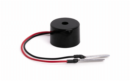
Buzzer is a kind of voice device that converts audio model into sound signal. It is mainly used to prompt or alarm. According to different design and application, it can produce music sound, flute sound, buzzer, alarm sound, electric bell and other different sounds.
Buzzers can be categorized into two different types – active buzzers and passive buzzers. An active buzzer has a built-in oscillator so it can produce sound with only a DC power supply.
A passive buzzer does not have a built-in oscillator, so it needs an AC audio signal to produce sound.
Active buzzers are the simplest to use. They are typically available in voltages from 1.5V to 24V. All you need to do is apply a DC voltage to the pins and it will make a sound. One downside of active buzzers is that the frequency of the sound is fixed and cannot be adjusted.
Passive buzzers need an AC signal to produce sound. the downside to this is that they will need more complex circuitry to control them, like an oscillating 555 timer or a programmable microcontroller like the Arduino.
Passive buzzers have the advantage that they can vary the pitch or tone of the sound. Passive buzzers can be programmed to emit a wide range of frequencies or musical notes.
Typical applications include siren, alarm device, fire alarm, air defense alarm, burglar alarm, timer, etc. It is widely used in household appliances, alarm system, automatic production line, low-voltage electrical equipment, electronic toys, game machines and other products and industries.
GebraBit Buzzer module
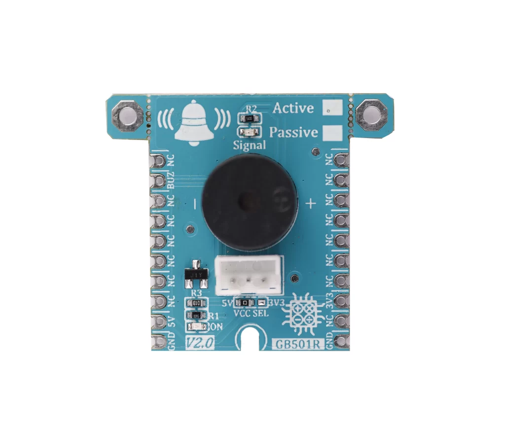
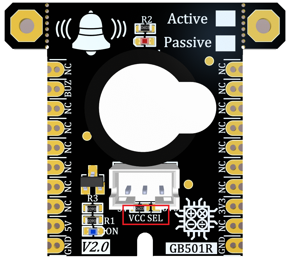
GebraBit BUZZER features active or passive BUZZER and can operate with “3V3” or “5V” supply Voltages by considered “VCC SEL” jumper selector.
The passive buzzer is an electromagnetic squeaker used to generate sound signals of different frequencies with PWM signals. The active buzzer is more simple than the passive and only needs a HIGH signal to produce a fixed frequency sound.
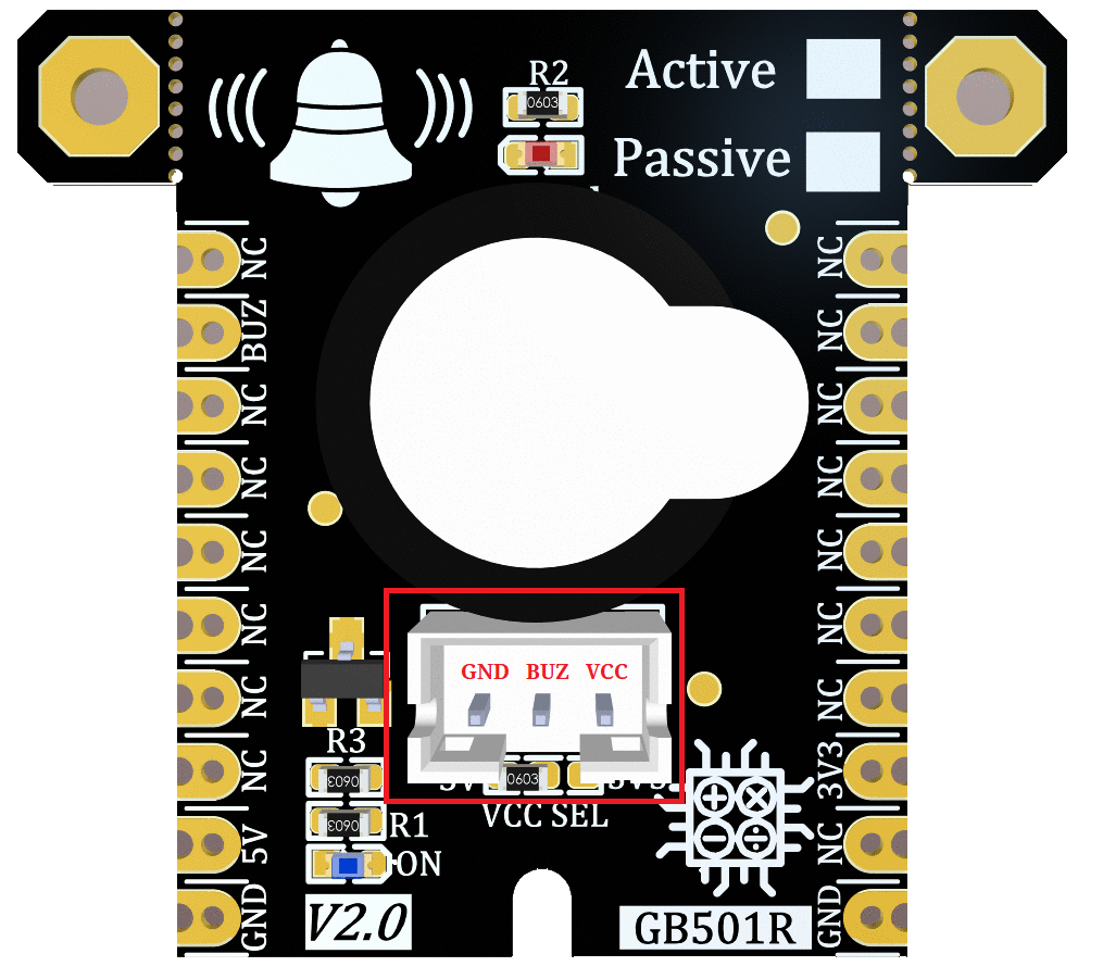
For easy accessibility, GebraBit BUZZER gives access to the “VCC“, “GND“, and “BUZ” pins by a 3-pin PH connector to extend them on other boards.
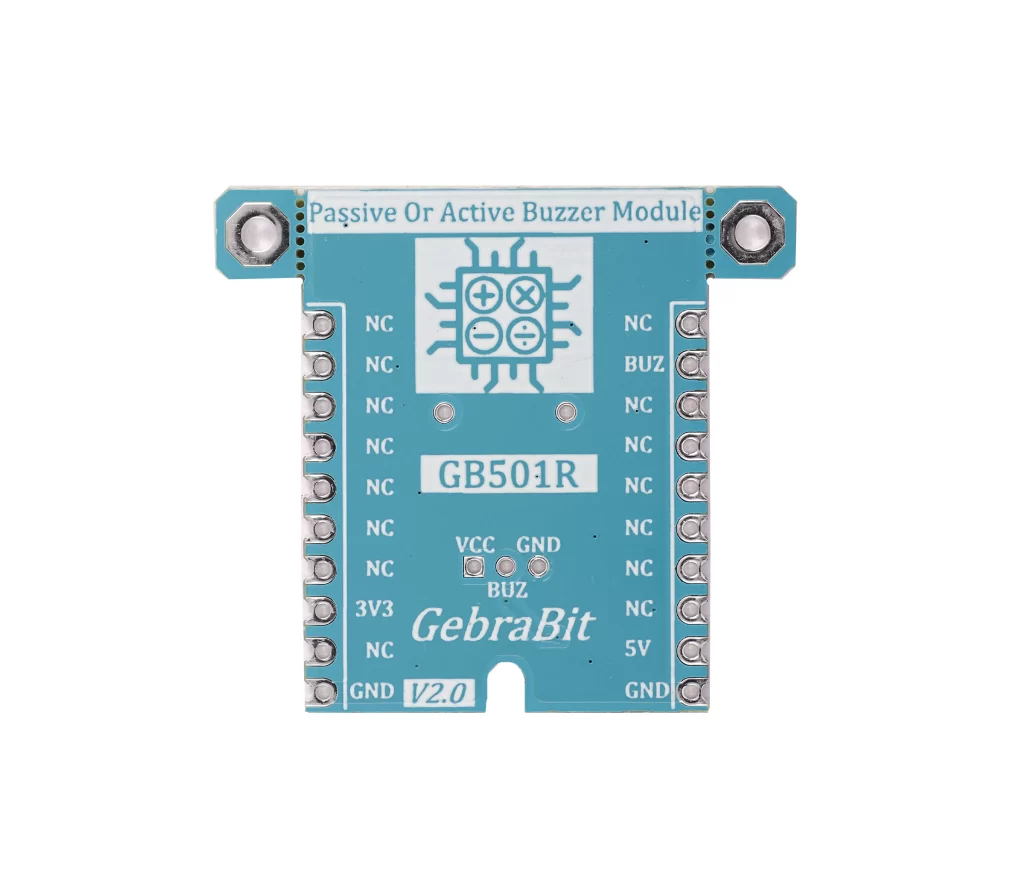
To start this module, just put the GebraBit Buzzer module in the BreadBoard, then start the module by applying the proper voltage. Due to the compatibility of the GebraBit Buzzer pins with the GebraBus standard and the presence of an internal 3V3 regulator on GebraBit microcontroller development modules, we recommend using GebraBit microcontroller development modules for testing and commissioning.
Module Specification
Module Application
- Module type: ActivePasive Buzzer
- Module Supply voltage: 3.3 V or 5.0 V
- Frequrency Range: 20 HZ to 20 KHZ
- Sound Output: 85dB
- Robotic
Module Key Features
- User-selectable module power supply voltage between 3V3 and 5V
- Control Pin access with PH connector
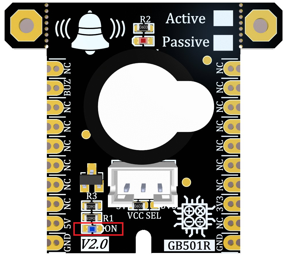
- On Board, ON/OFF LED indicator
- Signal LED indicator
- Pin Compatible with GEBRABUS
- It can be used as a daughter board of GebraBit MCU Modules
- Featuring Castellated pad (Assembled as SMD Part)
- Separatable screw parts to reduce the size of the board
- Package: GebraBit small (36.29mm x 32.72mm)
Introduction of module sections
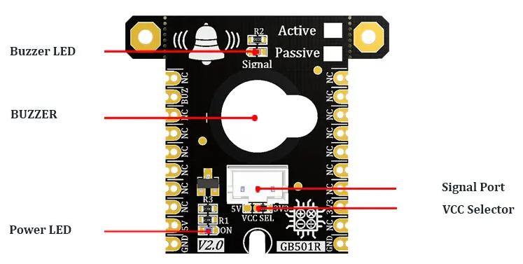
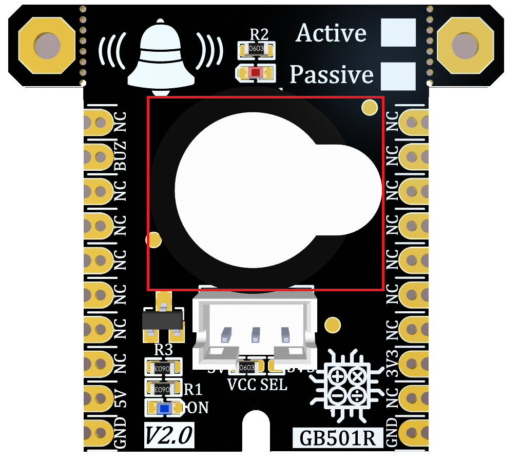
Buzzer
It’s the main part of this module which the output sound comes out of this part and is placed in the center of the module.
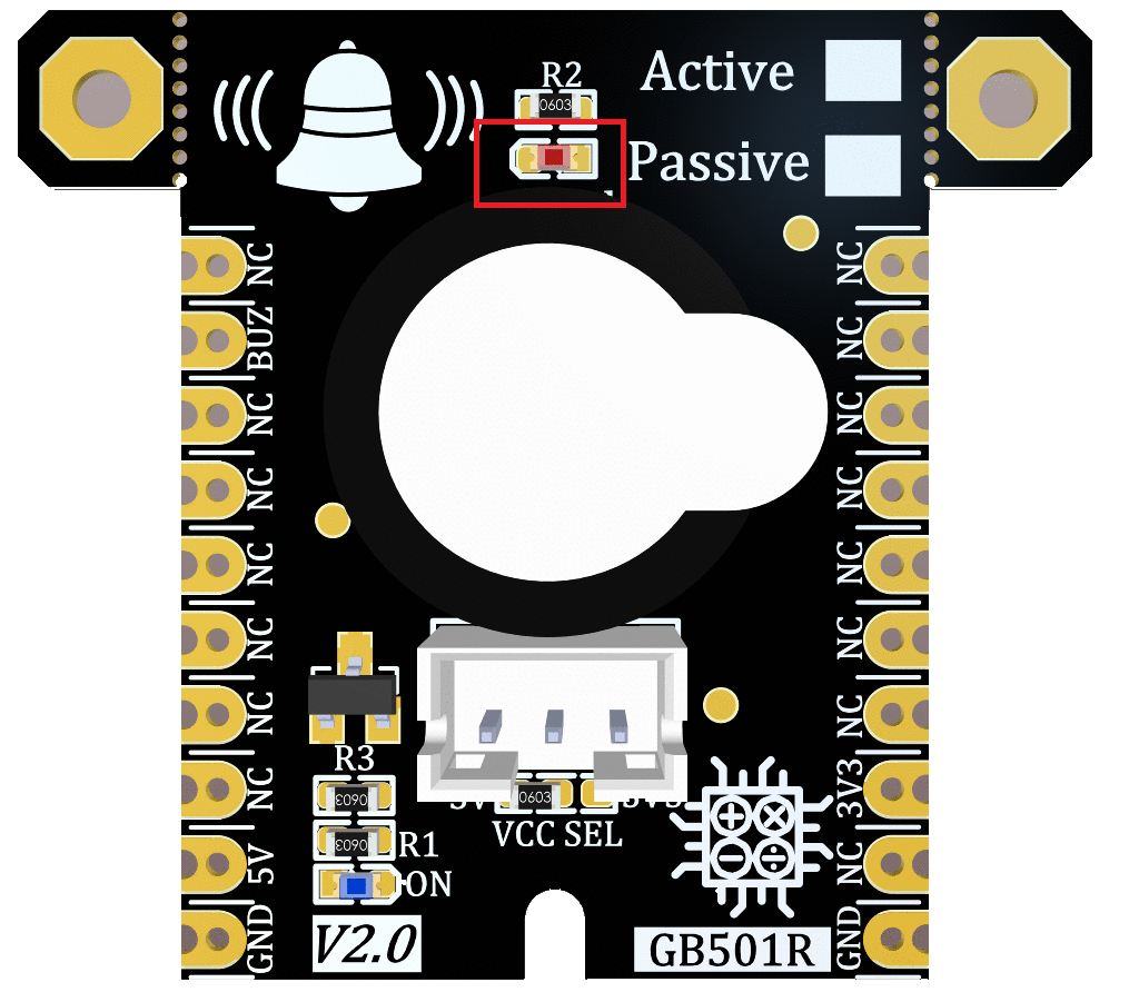
signal LED
The “Signal” LED indicates sound signal status when a “LOW” voltage is applied to the “BUZ” pin.
signal Port
For easy accessibility, GebraBit BUZZER gives access to the “VCC“, “GND“, and “BUZ” pins by a 3-pin PH connector to extend them on other boards.
VCC SEL jumper
According to the state of 0R resistance of this jumper, the module main supply voltage is selected between “5V” and “3V3”.
Power LED
According to the state of the “VCC SEL” jumper and by applying voltage to the module through the corresponding pin, this LED will be lit.
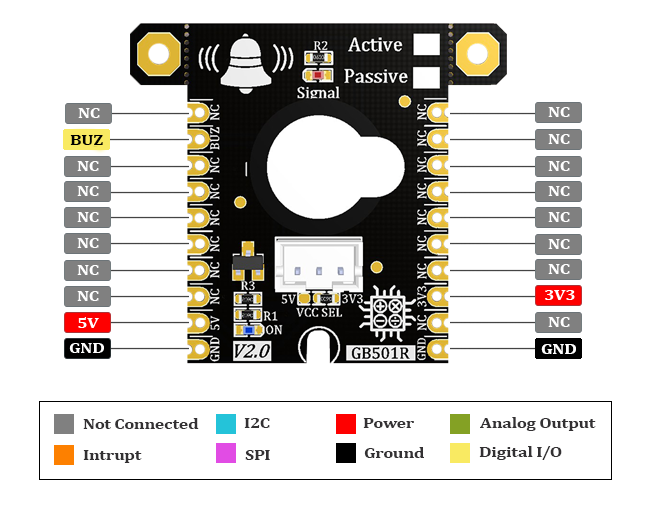
GebraBit Buzzer Module pins
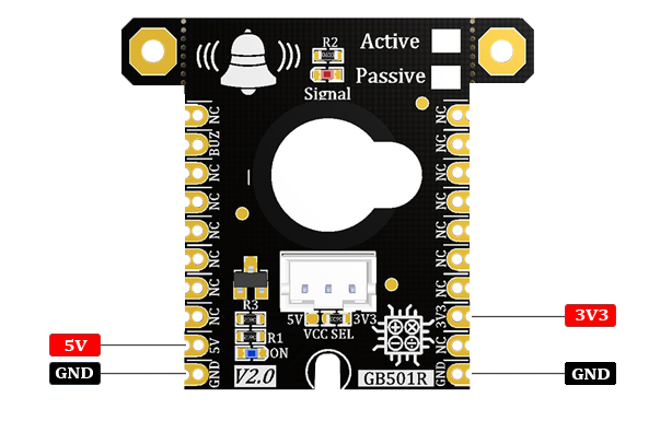
Supply pins
- 3V3 and 5V: These pins can provide the main power supply of the module according to the state of the “VCC SEL” Selector Jumper.
- GND: This is the ground pin of the module.
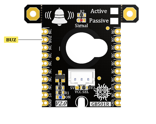
BUZ pin
The buzzer input signal is given to the GebraBit BUZZER module by the “BUZ” pin which is Active LOW.
Connect to the processor

connect to GebraBit ATMEGA32A and STM32F303
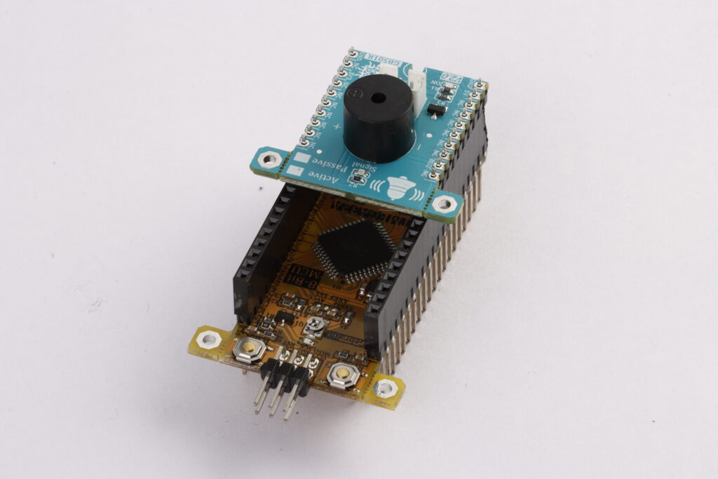
To Set-up the GebraBit Buzzer with the GebraBit ATMEGA32A or GebraBit STM32F303 you can simply place the GebraBit Buzzer module pin to pin on the GebraBit ATMEGA32A or GebraBit STM32F303 module and start the module by applying the proper voltage. Here the separate connection of the modules is shown for better understanding.
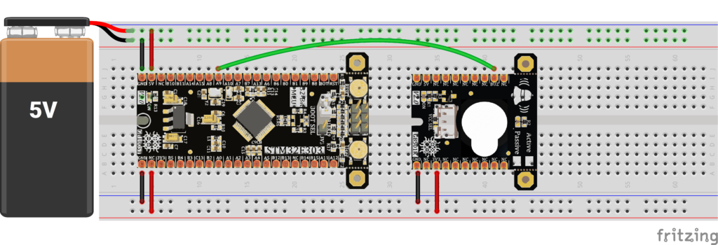
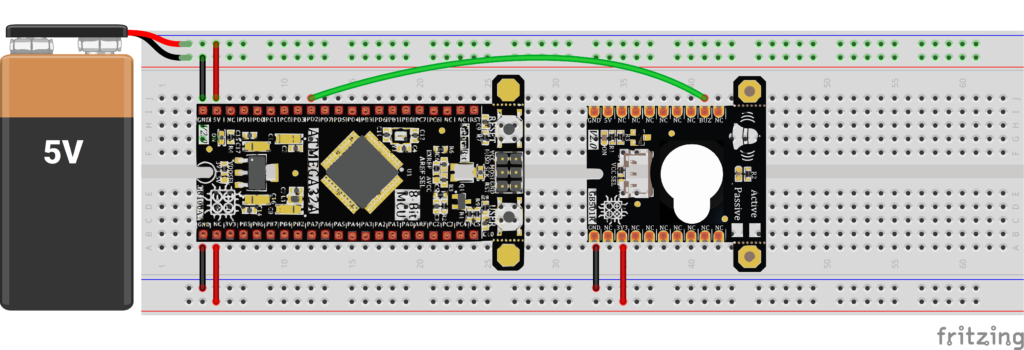
Note: If you are using GebraBit microcontroller modules, note that the “VCC SEL” jumper of GebraBit Buzzer module is set to “3V3” so that you can easily get “3V3” voltage from the microcontroller module.
connect to ARDUINO UNO
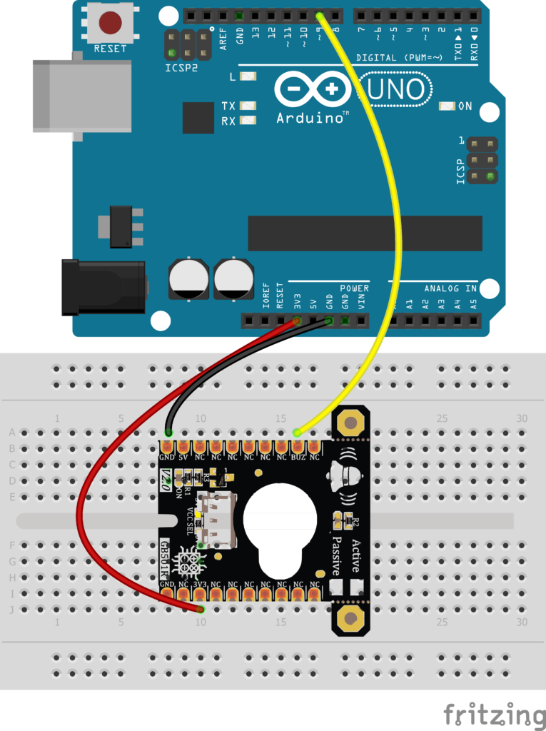
To set up with ARDOINO UNO, you just need to Place the GebraBit Buzzer module on the bread board and connect the “3V3” and “GND” pins of the Buzzer module to the “3V3” and “GND” pins of the Arduino board then connect the GebraBit Buzzer “BUZ” pin to one of the “PWM” pins (e.g. pin D9) of the ARDUINO UNO board.
You can see how to connect the above mentioned steps, in the below picture:
